
HP Integrity rx8620 Server User Service Guide
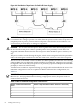

NOTE: Label the AC power cords during the installation. One suggestion is to use tie wraps
that have the flag molded into the tie wrap. The flag can be labeled using the appropriate two
characters to represent the particular AC power input (for example, A0). Another suggestion
would be to use color coded plastic bands. Use one color to represent the first pair A0/A1 and
another color to represent the second pair B0/B1 (provided a second power source is available
at the customer site).
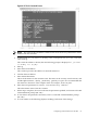
Applying Power to the Server
Initial observations can be made as to the functionality of the server before attaching any LAN
or serial cables, the system console, or any peripherals to the server. When an active AC power
source is first applied to the server, the following observations can be made at three different
intervals or points in time.
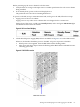
INTERVAL ONE The power has just been applied to the server but the front panel On/Off switch
is Off. The front air intake fans flash a dim red color, the bulk power supplies flash amber and
an amber light is present on the hard disk drives.
INTERVAL TWO After the power has been plugged into the server for about 30 seconds, the
standby power turns on and the front intake fan LED indicators turn solid green. The bulk power
supplies (BPS) flash green and the amber light is still present on the hard disk drives. The front
panel On/Off switch is Off at this interval. Housekeeping power is on at this point.
INTERVAL THREE With the On/Off switch on the front of the server set to On, the intake fans
spin up and become noticeably audible while the LED indicator remains solid green. The BPS
LED indicator turns a solid green and the PCI backplane power supply LED indicators turn solid
green. The hard disk drive LED turns green briefly and then the LED turns off.
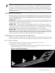
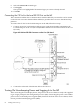
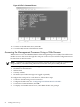
Installing the Line Cord Anchor (rack mounted servers)
The line cord anchor is attached to the rear of the server when rack mounted. It provides a method
to secure the line cords to the server, preventing accidental removal of the cords from the server.
Four Cell Server Installation
There are holes pre-drilled, and captive nuts pre-installed in the server chassis.
To install the line cord anchor, follow these steps:
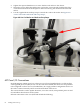
1. Align the line cord anchor thumbscrews with the corresponding captive nuts at the rear of
the chassis. See Figure 4-7: “Four Cell Line Cord Anchor ”,
Figure 4-7 Four Cell Line Cord Anchor
Connecting AC Input Power 63