
HP Integrity rx8620 Server User Service Guide
• One Ultra3 (160MB/sec) 68-pin SCSI port for connection to external SCSI devices by a very
high density cable interconnect (VHDCI) connector.
• One RJ-45 style 10Base-T/100Base-T/1000Base-T system LAN connector. This LAN uses
standby power and is active when AC is present and the front panel power switch is off.
• One RJ-45 style 10Base-T/100Base-T MP LAN connector. This LAN uses standby power and
is active when AC is present and the front panel power switch is off. This LAN is also active
when the front power switch is on.
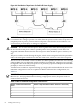
• Three RS-232 connectors provide connections for a local console, remote console, and a UPS.
UPS port—A system serial port for connection to a UPS or another system application. The
port is located near the top of the core I/O card near the external SCSI connector when the
card is installed in the server chassis.
Remote console port—A remote serial port for connection to a modem. The port is located
in the middle of the three RS-232 connectors.
Local console port—A local serial port for connection to a terminal. The port is located at
the bottom of the core I/O card when the card is installed in the server chassis.
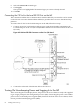
Internal connections for the core I/O board include the following:
• Three single ended (SE) internal SCSI buses for internal devices. These buses are routed to
the system board where they are cabled to a mass storage backplane.
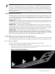
Setting Up the CE Tool (PC)
The CE Tool is usually on a laptop. It enables communication with the management processor
(MP) in the server. The MP monitors the activity of either a one-partition or a multiple-partition
configuration.
During installation, communicating with the MP enables such tasks as:
• Verifying that the components are present and installed correctly
• Setting LAN IP addresses
• Shutting down cell board power
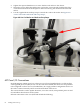
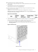
Communication with the MP is established by connecting the CE Tool to the local RS-232 port
on the core I/O card.
Setting CE Tool Parameters
After powering on the CE Tool, ensure the communications settings are as follows:
• 8/none (parity)
• 9600 baud
• None (Receive)
• None (Transmit)
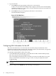
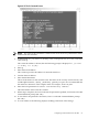
If the CE Tool is a laptop using Reflection 1, check or change these communications settings
using the following procedure:
1. From the Reflection 1 Main screen, pull down the Connection menu and select Connection
Setup.
2. Select Serial Port.
3. Select Com1.
4. Check the settings and change, if required.
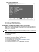
Go to More Settings to set Xon/Xoff.
5. To close the More Settings window, click OK.
6. To close the Connection Setup window, click OK.
7. Pull down the Setup menu and select Terminal (under the Emulation tab).
Setting Up the CE Tool (PC) 65