
Installation Guide, Sixth Edition - HP Integrity rx8620 Server

Chapter 2
Installation
Cabling and Power Up
77
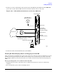
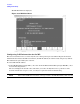
1. Connect one end of a null modem cable (9-pin to 9-pin) (Part Number 5182-4794) to the Local RS-232
port on the core I/O card (the DB9 connector located at the bottom of the core I/O card).
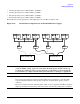
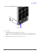
Figure 2-29 LAN and RS-232 Connectors on the Core I/O Board
2. Connect the other end of the RS-232 cable to the CE Tool.
Turning On Housekeeping Power and Logging in to the MP
After connecting the serial display device, the power to the server cabinet is ready to be supplied to get a login
prompt for the management processor (MP). Connecting the power cords allows power to flow to the bulk
power supplies (BPS) located at the front of the server cabinet, which in turn provides housekeeping power
(HKP).
Before powering up the server cabinet for the first time:
1. Verify that the AC voltage at the input source is within specifications for each server cabinet being
installed.
2. If not already done, power on the serial display device.
RS-232 UPS Port
SYSTEM LAN Port
RS-232 Remote Port
GSP LAN Port
RS-232 Local Port
5/23/01
KIN001
Other Serial Device
Core I/O Card
Customer Lan
System LAN
(Customer LAN)
( Assigned /dev/lan0 )
RS-232 UPS
RS-232 Remote
MP LAN
( Assigned /dev/lan1 )
via the RS-232 Local Port
is available once the MP is configured
Note: The ability to telnet to the MP LAN Port
RS-232 Local
Cable Part # 5182-4794
UPS (Optional) or
CE Tool (PC)
Modem