
HP Integrity rx8640 and HP 9000 rp8440 Servers Installation Guide


Connecting the CE Tool to the Local RS-232 Port on the MP
This connection enables direct communications with the MP. Only one window can be created on
the CE Tool to monitor the MP. When enabled, it provides direct access to the MP and to any
partition.
Use the following procedure to connect the CE Tool to the RS-232 Local port on the MP:
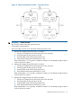
1. Connect one end of a null modem cable (9-pin to 9-pin) (Part Number 5182-4794) to the
RS-232 Local port on the core I/O card (the DB9 connector located at the bottom of the core
I/O card). See Figure 41.
Figure 41 LAN and RS-232 Connectors on the Core I/O Board
RS-232 UPS Port
SYSTEM LAN Port
RS-232 Remote Port
GSP LAN Port
RS-232 Local Port
System LAN
(Customer LAN -
Assigned /dev/lan0)
MP LAN
(Assigned /dev/lan1)
RS-232 Local Port
CE Tool
(PC)
NOTE: The ability to telnet to the MP LAN port is available once the MP is configured via
the RS-232 Local port.
2. Connect the other end of the RS-232 cable to the CE Tool.
Turning On Housekeeping Power and Logging In to the MP
After connecting the serial display device, the power to the server cabinet is ready to be supplied
to get a login prompt for the management processor (MP). Connecting the power cords allows
power to flow to the bulk power supplies (BPS) located at the front of the server cabinet, which in
turn provides housekeeping power (HKP).
Before powering up the server cabinet for the first time:
1. Verify that the AC voltage at the input source is within specifications for each server cabinet
being installed.
60 Installing the System