
HP Integrity rx8640, HP 9000 rp8440 Server User Service Guide
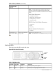
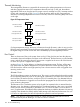

Table 33 Disk Drive LEDs (continued)
DescriptionFlash RateStatus LEDActivity LED
I/O Disk activityFlutter at rate of
activity
OffGreen
Predictive failure, needs immediate investigationFlashing at 1Hz or
2 Hz
YellowOff
Operator inducing manuallyFlashing at 0.5Hz
or 1Hz
YellowOff
Module fault, criticalSteadyYellowOff
Unit not powered or installedLEDs offOffOff
Interlock Switches
There are three interlock switches located in the server. Both side covers and the top cover have
an interlock switch located underneath each cover.
• Side Covers—If either side cover is removed while the system is powered on, the system fans
on the front and rear increase in speed to ensure adequate cooling. An event code is generated
to indicate a side cover was removed.
• Top Cover—If the top cover is removed while the system power is on, the PCI-X card cage
assembly I/O fan speed will not change. An event code is generated to indicate the top cover
was removed.
Server Management Subsystem Hardware Overview
Server management for the servers is provided by the MP on the core I/O board. The server
management hardware is powered by standby power that is available whenever the server is
plugged into primary AC power. This allows service access even if the DC power to the server is
switched off.
The management processor communicates with the server subsystems, sensors, and platform
dependent code (PDC) by internal buses. It also communicates with the operating console and
session gettys by universal asynchronous receiver-transmitters (UARTs) on the core I/O PCI bus.
Connection to the management processor is by way of three I/O paths:
• An RS-232 port for a local terminal
• An RS-232 port for a modem connection
• A 10/100/1000 baseT LAN port (Web console)
When the server is configured with one core I/O board, that board must be in slot 0, since the
master management processor is always the MP on the core I/O board in slot 0.
When the server is configured for two partitions, it must contain two core I/O boards, one for
each partition. It will also contain two MPs. In this case, the MP in slot 0 is the master MP and
provides all of the server management functions. The MP on the core I/O board in slot 1 is a slave
MP and redirects the operating system gettys to the master MP over an internal MP-to-MP link. All
external connections to the MP must be to the master MP in slot 0. The slave MP ports will be
disabled.
For high availability (HA), the server powers up and powers down without an MP. Booting HP-UX
without an MP depends on the ability of the operating system to boot without a console getty. Thus,
in a two-partition system, the partition with a failed MP may not boot, since the MP provides the
console getty.
The server configuration may not be changed without the MP.
In the event of a master MP failure, the slave MP automatically becomes the master MP.
122 Server Troubleshooting