
HP Integrity rx8640, HP 9000 rp8440 Server User Service Guide
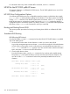

4. Execute the following EFI command:
map -r
NOTE: Each I/O card type and firmware image update may require a different flash utility
and procedure. Follow the instructions in the .txt file included with the latest HP IPF Offline
Diagnostic & Utilities CD.
5. Load the HP IPF Offline Diagnostic & Utilities CD.
The CD will contain the flash utility for IO each card type, firmware images, and a .txt file
that will include instructions and information about updating the firmware images.
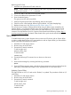
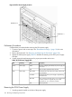
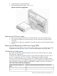
Removing and Replacing a PCI Smart Fan Assembly
The PCI smart fan assembly is located in front of the PCI card cage (Figure 88). The fan assembly
is a hot-swap component. See “Hot-Swap CRUs” (page 133) for a list and description of hot-swap
CRUs.
Figure 88 PCI Smart Fan Assembly Location
Front of Server
Top View
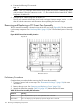
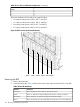
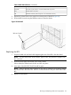
Preliminary Procedures
Complete these procedures before removing the PCI smart fan assembly.
1. Connect to ground with a wrist strap. See “Electrostatic Discharge ” (page 134) for more
information.
2. Remove the top cover. See “Removing and Replacing Covers” (page 136).
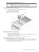
3. Identify the failed fan assembly. Table 35 (page 152) defines the fan LED states.
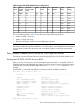
Table 35 Smart Fan Assembly LED Indications
MeaningLED State
Fan is at speed and in sync or not at speed less than 12 seconds.Green
Fan is not keeping up with speed/sync pulse for longer than 12 seconds.Flash Yellow
152 Removing and Replacing Components