
HP Integrity rx8640, HP 9000 rp8440 Server User Service Guide
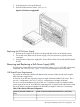

2. Firmly depress the securing thumb latch.
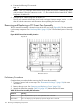
3. Slide the module from the chassis. See Figure 91.
Figure 91 PCI-X Power Supply Detail
Replacing the PCI-X Power Supply
1. Slide the power supply in the chassis until the thumb latch clicks into the locked position.
2. The module easily slides into the chassis; apply a slow, firm pressure to properly seat the
connection.
3. Verify the status of the power supply LEDs. Green LED should be ON and the fault LED should
be OFF.
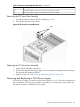
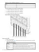
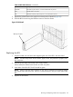
Removing and Replacing a Bulk Power Supply (BPS)
The bulk power supply (BPS) is located in the front of the chassis (Figure 92). The BPS is a hot-swap
component. See “Hot-Swap CRUs” (page 133) for a list and description of hot-swap CRUs.
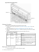
Cell Board Power Requirements
The number of cell boards installed will determine the minimum number of bulk power supplies
(BPS) required to support them.
A minimum of two BPS are required to support a single cell board installed in the server. This is
not a N+1 configuration. See Table 37 for N+1 configurations of multiple cell boards.
The server can accommodate a total of six BPSs. N+1 capability provides one additional bulk
power supply to fail over to. If one BPS fails, adequate power is supplied to the cell boards to keep
the server partitions operational. Replace the failed BPS promptly to restore N+1 functionality.
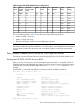
Table 37 N+1 BPS-to-Cell Board Configuration
Number of Operational BPS Installed to Maintain N+1 FunctionalityNumber of Cell Boards Installed in the
Server
31
42
Removing and Replacing a Bulk Power Supply (BPS) 155