
HP Integrity rx8640, HP 9000 rp8440 Server User Service Guide
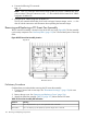
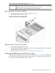
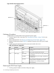
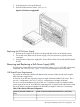
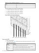
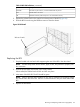
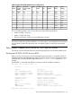
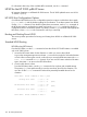

Table 37 N+1 BPS-to-Cell Board Configuration (continued)
Number of Operational BPS Installed to Maintain N+1 FunctionalityNumber of Cell Boards Installed in the
Server
53
64
The power distribution for the bulk power supplies follows:
• A0 input provides power to BPS 0, BPS 1, and BPS 2
• A1 input provides power to BPS 3, BPS 4, and BPS 5
• B0 input provides power to BPS 0, BPS 1, and BPS 2
• B1 input provides power to BPS 3, BPS 4, and BPS 5
Figure 92 BPS Location (Front Bezel Removed)
BPS 0 BPS 1 BPS 2
BPS 3
BPS 4
BPS 5
Removing the BPS
1. Remove the front bezel.
2. Isolate the failing BPS. Table 38 defines the states of the single multicolored LED on the BPS.
Table 38 BPS LED Definitions
DescriptionLED State
BPS in standby state and no faults or warnings are present.Blink Green
BPS in run state (48 volt output enabled) and no faults or warnings are present.Green
BPS in standby or run state and warnings are present but no faults.Blink Yellow
BPS in standby state, and recoverable faults are present but no non-recoverable faults.Yellow
156 Removing and Replacing Components