
HP Integrity rx8640, HP 9000 rp8440 Server User Service Guide

Central Processor Units
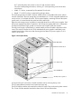
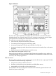
The cell board can hold up to four CPU modules. Each CPU module can contain up to two CPU
cores on a single die. Modules are populated in increments of one. On a cell board, the processor
modules must be the same family, type, and clock frequencies. Mixing of different processors on
a cell or a partition is not supported. See Table 1 for the load order that must be maintained when
adding processor modules to the cell board. See Figure 6 for the locations on the cell board for
installing processor modules.
NOTE: Unlike previous HP cell based systems, the server cell board does not require that a
termination module be installed at the end of an unused FSB. System firmware is allowed to disable
an unused FSB in the CC. This enables both sockets of the unused bus to remain unpopulated.
Table 1 Cell Board CPU Module Load Order
Socket 0Socket 1Socket 3Socket 2Number of
CPU Modules
Installed
CPU installedEmpty slotEmpty slotEmpty slot1
CPU installedEmpty slotEmpty slotCPU installed2
CPU installedCPU installedEmpty slotCPU installed3
CPU installedCPU installedCPU installedCPU installed4
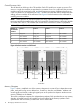
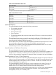
Figure 6 Socket Locations on Cell Board
Socket 2 Socket 3 Socket 1 Socket 0
Cell
Controller
Memory Subsystem
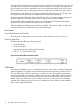
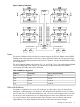
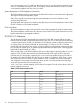
Figure 7 shows a simplified view of the memory subsystem. It consists of four independent access
paths, each path having its own address bus, control bus, data bus, and DIMMs . Address and
control signals are fanned out through register ports to the synchronous dynamic random access
memory (SDRAM) on the DIMMs.
The memory subsystem comprises four independent quadrants. Each quadrant has its own memory
data bus connected from the cell controller to the two buffers for the memory quadrant. Each
quadrant also has two memory control buses: one for each buffer.
16 HP Integrity rx8640 Server Overview