
HP Integrity rx8640, HP 9000 rp8440 Server User Service Guide
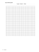
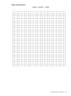

2. Cut and join them together (as necessary) to create a scale model floor plan of your computer
room.
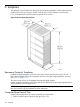
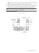
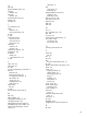
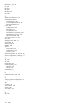
3. Remove a copy of each applicable equipment footprint template (Figure 95).
4. Cut out each template selected in step 3; then place it on the floor plan grid created in step
2.
5. Position pieces until you obtain the desired layout, then fasten the pieces to the grid. Mark
locations of computer room doors, air-conditioning floor vents, utility outlets, and so on.
NOTE: Attach a reduced copy of the completed floor plan to the site survey. HP installation
specialists use this floor plan during equipment installation.
Figure 95 Server Cabinet Template
Computer Room Layout Plan 171