
HP Integrity rx8640, HP 9000 rp8440 Server User Service Guide
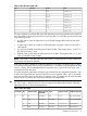
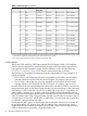
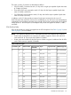
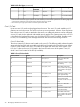
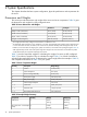
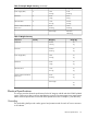
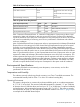
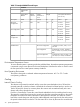

Table 7 PCI-X Slot Types (continued)
PCI Mode SupportedSupported CardsRopesMaximum Peak
Bandwidth
Maximum MHzSlot
1
I/O Partition
PCI-X Mode 23.3 V or 1.5 V014/0152.13 GB/s2664
PCI-X Mode 23.3 V or 1.5 V012/0132.13 GB/s2663
PCI or PCI-X Mode
1
3.3 V010/0111.06 GB/s1332
PCI or PCI-X Mode
1
3.3 V008/0091.06 GB/s1331
PCI or PCI-X Mode
1
3.3 V001533 MB/s668
2
1
PCI or PCI-X Mode
1
3.3 V002/0031.06 GB/s1337
PCI-X Mode 23.3 V or 1.5 V004/0052.13 GB/s2666
PCI-X Mode 23.3 V or 1.5 V006/0072.13 GB/s2665
PCI-X Mode 23.3 V or 1.5 V014/0152.13 GB/s2664
PCI-X Mode 23.3 V or 1.5 V012/0132.13 GB/s2663
PCI or PCI-X Mode
1
3.3 V010/0111.06 GB/s1332
PCI or PCI-X Mode
1
3.3 V008/0091.06 GB/s1331
1
Each slot will auto select the proper speed for the card installed up to the maximum speed for the slot. Placing high speed
cards into slow speed slots will cause the card to be driven at the slow speed.
2
Slot is driven by a single rope and has a maximum speed of 66 MHz.
PCIe Backplane
The 16–slot (8 PCI and PCI-X; 8 PCI-Express) mixed PCI-X/PCI-Express (“PCIe”) I/O backplane
was introduced for the Dual-Core Intel® Itanium® processor 9100 Series release and is heavily
leveraged from the PCI-X backplane design. Only the differences will be descibed here. See
“PCI/PCI-X I/O Subsystem” (page 20) for common content between the two boards..
The PCI-Express I/O backplane comprises two logically independent I/O circuits (partitions) on
one physical board.
• The I/O chip in cell location zero (0) and its associated four PCI-X ASICs, four PCIe ASICs,
and their respective PCI/PCI-X/PCIe slots form PCI-Express I/O partition 0 plus core I/O.
• The I/O chip in cell location one (1) and its associated four PCI-X ASICs, four PCIe ASICs,
and their respective PCI/PCI-X/PCIe slots form PCI-Express I/O partition 1 plus core I/O.
Each PCI/PCI-X slot has a host-to-PCI bridge associated with it, and each PCIe slot has a host-to-PCIe
bridge associated with it. A dual slot hot swap controller chip and related logic is also associated
with each pair of PCI or PCIe slots. The I/O chip on either cell location 0 or 1 is a primary I/O
system interface. Upstream, the I/O chips communicate directly with the cell controller ASIC on
the host cell board via a high bandwidth logical connection known as the HSS link.When installed
in the SEU chassis within a fully configured system, the ASIC on cell location 0 connects to the cell
controller chip on cell board 2, and the ASIC on cell location 1 connects to the cell controller chip
on cell board 3 through external link cables.
Downstream, the ASIC spawns 16 logical 'ropes' that communicate with the core I/O bridge on
the system backplane, PCI interface chips, and PCIe interface chips. Each PCI chip produces a
single 64–bit PCI-X bus supporting a single PCI or PCI-X add-in card. Each PCIe chip produces a
single x8 PCI-Express bus supporting a single PCIe add-in card.
22 HP Integrity rx8640 Server Overview