
HP Integrity rx8640, HP 9000 rp8440 Server User Service Guide

VGA Consoles
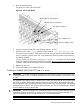
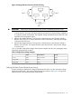
Any device that has a PCI section in its path and does not have a UART section will be a VGA
device. If you require a VGA console, choose the device and unmark all others. Figure 30 shows
that a VGA device is selected as the console.
Interface Differences Between Itanium-based Systems
Each Itanium-based system has a similar interface with minor differences. Some devices may not
be available on all systems depending on system design or installed options.
Other Console Types
Any device that has a UART section but no PCI section is a system serial port. To use the system
serial port (if available) as your console device, select the system serial device entry that matches
your console type (PcAnsi, Vt100, Vt100+, VtUtf8) and deselect everything else.
If you choose either a system or MP serial port HP recommends that you use a vt100+ capable
terminal device.
Additional Notes on Console Selection
Each Operating System makes decisions based on the EFI Boot Maintenance Manager menu’s
Select Active Console selections to determine where to send its output. If incorrect console devices
are chosen the OS may fail to boot or will boot with output directed to the wrong location. Therefore,
any time new potential console devices are added to the system or anytime NVRAM on the system
is cleared console selections should be reviewed to ensure that they are correct.
Cabling and Powering On the Server
After the system has been unpacked and moved into position, it must be connected to a source of
AC power. The AC power must be checked for the proper voltage before the system is powered
up. This chapter describes these activities.
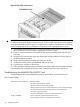
Checking the Voltage
This section provides voltage check information for use on the customer site. The emphasis is on
measuring the voltages at the power cord plug end specified as an IEC-320 C19 type plug. This
is the end that plugs directly into the back of the server cabinet.
NOTE: Perform these procedures for each power cord that will be plugged directly into the back
of the server cabinet. If you do not obtain the expected results from this procedure during the
voltage check, See the section titled “Voltage Check (Additional Procedure)” (page 62).
Verifying the Voltage Range of the Recptacle
Use this procedure to measure the voltage between L1 and L2, L1 to ground, and L2 to ground.
See Figure 31 for voltage reference points when performing the following measurements.
58 Installing the System