
HP Integrity rx8640, HP 9000 rp8440 Server User Service Guide
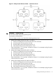
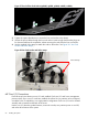

4. Measure the voltage between A1 and B1 as follows:
1. Take the AC voltage down to the lowest scale on the volt meter.
2. Insert the probe into the ground pin for A1.
3. Insert the other probe into the ground pin for B1.
4. Verify that the measurement is between 0-5 V AC.
If the measurement is 5 V or greater, escalate the situation. Do not attempt to plug the power
cord into the server cabinet.
Voltage Check (Additional Procedure)
The voltage check ensures that all phases (and neutral, for international systems) are connected
correctly to the cabinet and that the AC input voltage is within limits.
Perform this procedure if the previous voltage check procedure did not yield the expected results.
NOTE: If you use an uninterrupted power supply (UPS), see applicable UPS documentation for
information on connecting the server and checking the UPS output voltage. UPS user documentation
is shipped with the UPS. Documentation is also available at: http://www.hp.com/go/bizsupport.
1. Verify that site power is OFF.
2. Open the site circuit breakers.
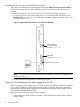
3. Verify that the receptacle ground connector is connected to ground. See Figure 34 for connector
details.
4. Set the site power circuit breaker to ON.
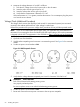
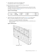
Figure 34 Wall Receptacle Pinouts
5. Verify that the voltage between receptacle pins X and Y is between 200–240 V AC.
WARNING! SHOCK HAZARD
Risk of shock hazard while testing primary power.
Use properly insulated probes.
Be sure to replace access cover when finished testing primary power.
6. Set the site power circuit breaker to OFF.
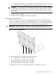
7. Route and connect the server power connector to the site power receptacle.
62 Installing the System