
HP Integrity rx8640, HP 9000 rp8440 Server User Service Guide
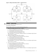
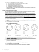
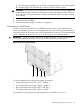
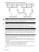
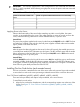
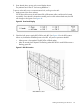

Figure 36 Distribution of Input Power for Each Bulk Power Supply
WARNING! Voltage is present at various locations within the server whenever a power source
is connected. This voltage is present even when the main power switch is in the off position. To
completely remove power, all power cords must be removed from the server. Failure to observe
this warning could result in personal injury or damage to equipment.
CAUTION: Do not route data and power cables together in the same cable management arm.
Do not route data and power cables in parallel paths in close proximity to each other. The suggested
minimum distance between the data and power cables is 3 inches (7.62 cm).
The power cord has current flowing through it, which creates a magnetic field. The potential to
induce electromagnetic interference in the data cables exists, which can cause data corruption.
NOTE: Label the AC power cords during the installation. One suggestion is to use tie wraps that
have the flag molded into the tie wrap. The flag can be labeled using the appropriate two characters
to represent the particular AC power input (for example, A0). Another suggestion would be to use
color coded plastic bands. Use one color to represent the first pair A0/A1 and another color to
represent the second pair B0/B1 (provided a second power source is available at the customer
site).
The server can accomodate a total of six BPSs. N+1 BPS capability describes the server having
adequate BPSs plus one additional module installed. If one BPS fails, adequate power will still be
supplied to the cell board(s) to keep the server partition(s) operational. Replace the failed BPS
promptly to restore N+1 functionality.
A minimum of two BPS are required to bring up a single cell board installed in the server. This
minimum configuration is not N+1 capable. See Table 23 (page 65) for BPS to cell board N+1
configurations.
The minimum N+1 configuration for the HP Integrity rx8640 server requires 2 cell boards and 4
BPS modules. The BPS modules must be installed per the following rules:
• BPS slots 0 and 1 must contain a BPS module for Grid A0–B0
• BPS slots 3 and 4 must contain a BPS module for Grid A1–B1
Installing the BPS modules per these rules ensures a balanced N+1 distribution of power to each
grid.
64 Installing the System