
HP Integrity rx8640, HP 9000 rp8440 Server User Service Guide

2. If not already done, power on the serial display device.
The preferred tool is the CE Tool running Reflection 1.
To power on the MP, set up a communications link, and log in to the MP:
1. Apply power to the server cabinet.
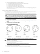
On the front of the server, the MP Status LED will illuminate yellow until the MP is booted
successfully. Once the MP is booted successfully, and no other cabinet faults exist, the LED
will change to solid green. See Figure 40.
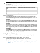
Figure 40 Front Panel Display
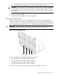
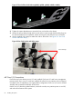
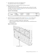
2. Check the bulk power supply (BPS) LED for each BPS. See Figure 41 for the LED location.
When on, the breakers distribute power to the BPS. AC power is present at the BPS:
• When power is first applied. The BPS LEDs will flash amber.
• After 30 seconds have elapsed. The flashing amber BPS LED for each BPS becomes a
flashing green LED.
Figure 41 BPS LED Location
BPS LED Location
Cabling and Powering On the Server 69