
Installation Guide, Third Edition - HP Integrity rx8640 SEU

contains clock generation circuits, manageability circuits, DC-to-DC converters, power monitor
logic, and fan control.
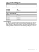
Core IO Backplane Module
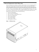
The core IO backplane is housed in a separate sheet metal module holding the backplane and
the core IO boards. This module can be removed from the rear of the chassis for easy access to
the core IO backplane.
The module adapts the core IO sockets in a horizontal mounting position to the system backplane,
which is mounted vertically. It contains the lower bus adapter (LBA), PCI bridges that convert
the ropes links from the PCI backplane to the PCI bus interface where the core IO card is inserted.
It also drives the PCI clocks and voltage regulators that provide domain power to the core IO
cards.
Core IO PCA
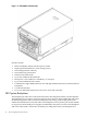
There are two core IO boards plugged into the SEU system when shipped. The core IO boards
are oriented horizontally and are accessed from the back of the SEU. They are not a standard
PCI form factor. Each core IO contains the required core functions to support a partition in a
server. Each also contains a manageability processor (MP).
Neither of the MPs on the core IO cards installed in the SEU can become the primary MP for the
server and SEU combination. The primary MP for the server and SEU will always be one of the
core IO cards installed in the server.
When a server with an SEU is attached and configured for four partitions, there must be four
core IO boards, one for each partition. For this configuration, one core IO card in the server is
the primary MP and will provide all of the server management functions. The second core IO in
the server is the secondary MP. The third and fourth core IO cards located in the SEU have similar
primary and secondary characteristics but only within the SEU itself. Overall system management
for the combination of the server and the SEU is managed by the primary core IO in the server.
Console data from the SEU is directed to the server.
The core IO cards in the SEU support the mass storage and removable media devices and make
them available to the server in the same manner as the servers internal devices. The core IO card
in the upper slot is the secondary core IO card in the SEU and is associated with cell 3 in the main
server cabinet. The core IO card in the lower slot is the primary core IO card in the SEU and is
associated with cell 2 in the main server cabinet.
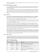
Core IO Boot Paths
The SEU internal IO devices are located on the core IO. The following table outlines the paths
assigned to the hard disk and removable media disk bays located on the front of the SEU cabinet.
Core IO card 2 refers to the core IO located in the bottom slot at the rear of the system. Core IO
card 3 refers to the core IO card located in the top slot at the rear of the system. Core IO cards 0
and 1 are located in the server.
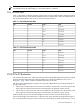
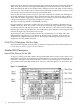
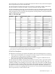
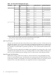
Table 1-1 SEU Core IO Boot Path
DescriptionPathDeviceCore IO card
The SYS LAN connector located on core IO 2.2/0/0/1/01 Gb LAN2
Hard drive located in the top left disk bay.2/0/0/2/0.6.0SCSI drive2
Removable media DVD (X = 2) or DDS-4 (X = 3) tape drive
located in the upper disk bay.
2/0/0/2/1.X.0SCSI drive2
Hard drive located in the top right disk bay.2/0/0/3/0.6.0SCSI drive2
SCSI drive connected to the external SCSI Ultra3 connector on
the core IO card.
2/0/0/3/1SCSI drive2
Core IO Backplane Module 13