
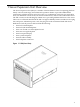
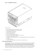
Installation Guide, Third Edition - HP Integrity rx8640 SEU

NOTE: Fans driven to a high RPM in dense air cannot maintain expected RPM and will be
considered bad by the MP leading to a “False Fan Failure” condition.
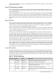
PCI-X Slot Boot Paths
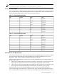
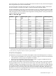
Table 1-3 and Table 1-3 list the mapping of PCI-X slots to ropes and boot paths. Pathing will have
to be modified for PCI cards that have different devices and functions. The cell column refers to
the cell board installed in the server in cell slot 2 and in cell slot 3
Table 1-2 Cell 2 PCI Slot Boot Paths
PathRopesPCI SlotCell
2/0/8/1/08/912
2/0/10/1/010/1122
2/0/12/1/012/1332
2/0/14/1/014/1542
2/0/6/1/06/752
2/0/4/1/04/562
2/0/2/1/02/372
2/0/1/1/0182
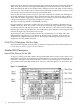
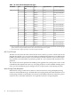
Table 1-3 Cell 3 PCI Slot Boot Paths
PathRopesPCI SlotCell
3/0/8/1/08/913
3/0/10/1/010/1123
3/0/12/1/012/1333
3/0/14/1/014/1543
3/0/6/1/06/753
3/0/4/1/04/563
3/0/2/1/02/373
3/0/1/1/0183
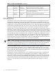
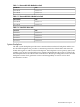
PCI-X/PCIe IO Backplane
The 16-slot (8 PCI and PCI-X; 8 PCI express) mixed PCI-X/PCIe IO backplane is heavily leveraged
from the PCI-X backplane design. Only the differences will be described here. See “PCI-X
Backplane” (page 14) for common content between the two boards.
The PCI express IO Backplane comprises two logically independent IO circuits (partitions) on
one physical board:
• The IO chip in cell location zero and its associated four PCI-X ASICs, four PCIe ASICs, and
their respective PCI/PCI-X/PCIe slots form PCIexpress IO partition 0 plus core IO.
• The IO chip in cell location one and its associated four PCI-X ASICs, four PCIe ASICs, and
their respective PCI/PCI-X/PCIe slots form PCIexpress IO partition 1 plus core IO.
Each PCI/PCI-X slot has a host-to-PCI bridge associated with it, and each PCIe slot has a
host-to-PCIe bridge associated with it. A dual slot hot swap controller chip and related logic is
also associated with each pair of PCI or PCIe slots. The IO chip on either cell location 0 or 1 is a
PCI-X/PCIe IO Backplane 15