
Installation Guide, Third Edition - HP Integrity rx8640 SEU

primary IO system interface. Upstream, the IO chips communicate directly with the cell controller
ASIC on the host cell board via a high bandwidth logical connection known as the HSS link.
When installed in the SEU chassis within a fully configured system, The ASIC on cell location 0
connects to the cell controller chip on cell board 2 and the ASIC on cell location 1 connects to the
cell controller chip on cell board 3 through external link cables.
Downstream, the ASIC spawns 16 logical 'ropes' that communicate with the core IO bridge on
the system backplane, PCI interface chips, and PCIe interface chips. Each PCI chip produces a
single 64-bit PCI-X bus supporting a single PCI or PCI-X add-in card. Each PCIe chip produces
a single x8 PCIexpress bus supporting a single PCIe add-in card.
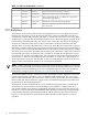
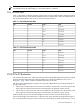
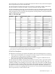
The ropes in each IO partition are distributed as follows:
One PCI-X ASIC is connected to each IO chip with a single rope capable of peak data rates of
533MB/s (PCIX-66). Three PCI-X ASICs are connected to each IO chip with dual ropes capable
of peak data rated of 1.06 GB/s (PCIX-133). Four PCIe ASICs are connected to each IO chip with
dual fat ropes capable of peak data rates of 2.12 GB/s (PCIe x8). In addition, each IO chip provides
an external single rope connection for the core IO.
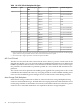
Each PCIexpress slot on the PCI-X/PCIe IO board is controlled by its own ASIC and is also
independently supported by its own half of the dual hot swap controller. All PCIe slots are
designed to be compliant with PCIe Rev.1.0. The PCIexpress IO backplane will provide slot
support for VAUX3.3, SMB*, and JTAG.
PCI-X/PCIe IO Backplane Slot Boot Paths
PCI-X/PCIe IO backplane slot boot paths are directly leveraged from the PCI-X backplane. See
“PCI-X Slot Boot Paths” (page 15) for more details.
Detailed SEU Description
Internal Disk Devices for the SEU
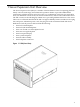
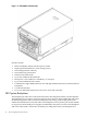
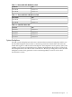
As Figure 1-3 shows, in an SEU cabinet, the top internal disk drives connect to cell 2 in the server
through the Core IO for cell 2. The bottom internal disk drives connect to cell 3 through the core
IO for cell 3. The upper removable media drive connects to cell 2 through the core IO card for
cell 2 and the lower removable media drive connects to cell 3 through the core IO card for cell
3.
Figure 1-3 Internal Disks
16 Server Expansion Unit Overview