
Installation Guide, Third Edition - HP Integrity rx8640 SEU

Side Cover Removal
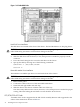
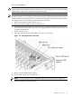
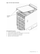
Figure 2-11 Side Cover Removal
1. Loosen the blue retaining screw securing the side cover to the chassis. (See Figure 2-11.) The
screw is located at the bottom of the server chassis.
2. Slide the cover from the chassis toward the rear of the system.
3. Place the cover in a safe location.
After removing the side cover, the system backplane is visible.
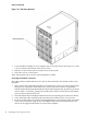
Connecting E-Link Cables to the Server
The cables will be routed inside the server chassis and connected to the shrouds on the server
backplane.
1. Remove the E-link cable bridge bracket, located at the rear of the server chassis in the upper
right side, by turning the two thumbscrews counterclockwise. Lift the U-shaped SBA
hold-down bracket positioned behind the E-link cable bridge bracket up and away from the
chassis. With a screwdriver, gently pop the filler plates away from the chassis. Discard the
parts just removed from the server.
2. Insert the E-link cable assembly bracket tab into the corresponding slot in the server chassis.
3. Screw the E-link cable assembly bracket attached to the cables into the server chassis.
4. Route each cable along the outside of the backplane down to the shrouds. Match each cable
to the shroud connector using the key on the REO Cable Instructions label affixed to the
chassis on the upper left-hand side as you face the backplane.
40 Installing the Server Expansion Unit