
Site Preparation Guide, Third Edition - HP Integrity rx8640 Server Expansion Unit
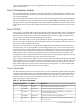
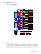
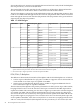

Detailed SEU Description
Figure 1-3 SEU Block Diagram
Slot1_8
Slot1_7
Slo1_6
Slo1_5
Slo1_4
Slot1_3
Slot1_2
Slot1_1
Slot0_8
Slot0_7
Slot0_6
Slot0_5
Slot0_4
Slot0_3
Slot0_2
Slot0_1
Gemini
ASIC
Gemini
ASIC
Gemini
ASIC
Gemini
ASIC
Gemini
ASIC
Gemini
ASIC
Mercury
ASIC
Gemini
ASIC
Gemini
ASIC
Gemini
ASIC
Gemini
ASIC
Gemini
ASIC
Gemini
ASIC
Gemini
ASIC
Mercury
ASIC
PCI-X 133MHZ Bus
Escalante
ASIC
1
Escalante
ASIC
0
Dual
HotSwap
Controller
PCI-X 66/133MHZ Bus
PCI-X 266MHZ Bus
PCI-X 266MHZ Bus
PCI-X 266MHZ Bus
PCI-X 266MHZ Bus
PCI-X 133MHZ Bus
PCI-X 133MHZ Bus
PCI-X 66/133MHZ Bus
PCI-X 133MHZ Bus
PCI-X 266MHZ Bus
PCI-X 266MHZ Bus
P
C
I
-
X
2
6
6
M
H
Z
B
u
s
PCI-X 266MHZ Bus
PCI-X 133MHZ Bus
PCI-X 133MHZ Bus
Single Rope to Core I/O 1
Single Rope to Core I/O 0
VRM 0
Rope100
Manageability
&
Hot Swap
FPGA
Rope113
Rope112
Rope111
Rope110
Rope000
Rope104
Rope105
Rope106
Rope107
Rope117
Rope116
Rope115
Rope114
Rope004
Rope005
Rope006
Rope007
Rope017
Rope016
Rope015
Rope014
Rope101
Rope102
Rope103
Rope001
Rope002
Rope003
Rope013
Rope012
Rope011
Rope010
VRM 1 VRM 2 VRM 3
+1.5V
Gemini
ASIC
E-Link to Cell 1
or Cell 3
PCI Power
PCI Power
+12V+3.3V +5V -12V
+3.3V_
STBY
+3.3V_STBY
+12V_
STBY
+12V_STBY
Mass Storage Power
IO Fan
Power
48V
48V
8MHz
Osc
LEDs
LEDs
LEDs
LEDs
LEDs
LEDs
LEDs
LEDs
LEDs
LEDs
LEDs
LEDs
LEDs
LEDs
LEDs
LEDs
+3.3V_STBY
+3.3V
+1.5V
+1.2V
Esca0 JTAG
&
Config.
Esca1 JTAG
&
Config.
Merc. & Gemini JTAG
PS Control & Status
CLK Gen,
Filters,
Vregs
Misc.
Dual
HotSwap
Controller
Dual
HotSwap
Controller
Dual
HotSwap
Controller
Dual
HotSwap
Controller
Dual
HotSwap
Controller
Dual
HotSwap
Controller
Dual
HotSwap
Controller
+3.3VAUX +3.3V +5V +12V -12V VIO
+3.3V +5V +12V -12V+3.3VAUX
+3.3V +5V +12V -12V+3.3VAUX
+3.3V +5V +12V -12V+3.3VAUX
+3.3V +5V +12V -12V+3.3VAUX
+3.3V +5V +12V -12V+3.3VAUX VIO
+3.3V +5V +12V -12V+3.3VAUX
+3.3V +5V +12V -12V+3.3VAUX VIO
VIO
E-Link to Cell 0
or Cell 2
8MHz
Osc
Config.
ROM
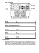
Internal Disk Devices for the SEU
As Figure 1-4 shows, in an SEU cabinet, the top internal disk drives connect to cell 2 in the server
through the Core I/O for cell 2. The bottom internal disk drives connect to cell 3 through the core
I/O for cell 3. The upper removable media drive connects to cell 2 through the core I/O card for
cell 2 and the lower removable media drive connects to cell 3 through the core I/O card for cell
3.
Detailed SEU Description 17