
User Service Guide, Fifth Edition - HP Integrity rx8640 SEU


4. Tighten the two blue-colored captive screws (lower left and upper right sides).
5. Replace the bezel.
NOTE: The fan LED will show that the fan is operational (green).
Removing and Replacing a Standby/Main Fan (Rear) Assembly
The Rear Standby/Main fan Assembly is located in the rear of the chassis. The fan assembly is a
hot swap component.
CAUTION: Observe all ESD safety precautions before attempting this procedure. Failure to
follow ESD safety precautions could result in damage to the SEU.
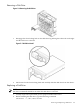
Figure 5-9 Rear Standby/Main Fan Assembly Locations
Removing and Replacing the Rear Standby/Main fan Assembly
The rear standby/main fan assembly is located in the rear of the chassis.
CAUTION: Observe all ESD safety precautions before attempting this procedure. Failure to
follow ESD safety precautions could result in damage to the server.
Removing the Rear Standby/Main Fan Assembly
1. Identify the failed fan assembly. The table below defines the fan LED states.
Table 5-3 Standby/Main Fan Assembly LED Indications
MeaningLED State
Fan is at speed and in sync or not at speed less than 12 secondsOn Green
Fan is not keeping up with speed/sync pulse for greater than 12 secondsFlash Yellow
Fan failed or stalled, has run slow, or fast for greater than 12 secondsRed
Fan is not present, or no power is applied to fan, or the fan has failedOff
Removing and Replacing a Standby/Main Fan (Rear) Assembly 105