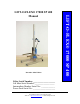
December 2001 Edition Lifter Serial Number: _____________________ Lift Mast Serial Number: ___________________ Intermediate Member Serial No.: _____________ Power Pack Serial No.: _____________________ RONI, LLC, 9311 Monroe Road, Suite D, Charlotte, NC 28270 Tel (7040 847-2464; Fax (704) 847-6739 Web site: http://www.roni.com E-mail: info@roni.
Lift-O-Flex™ 17000 SP 400 Manual TABLE OF CONTENTS 1. LIFT-O-FLEX 17000 SP 400 ............................................................................................................................2 1.1 2. ASSEMBLY INSTRUCTIONS............................................................................................................................4 2.1 3. Warranty .......................................................... 3 Assembly ..........................................................
Lift-O-Flex 17000 SP 400 Manual 1. LIFT-O-FLEX 17000 SP 400 LIFT-O-FLEX® is a registered trademark of RONI, LLC, Charlotte NC. NOTE: It is important that you read and fully understand this manual before using your LiftO-FlexLifter. If you have any questions contact your distributor or the manufacturer.
Lift-O-Flex 17000 SP 400 Manual OPERATIONAL SAFETY The ergonomic design of LIFT-O-FLEX is by itself an active factor of operational safety. Other factors of security and technical features are as follows: • The movement of the load platform will stop should an object be placed in-between the lift frame and the load platform or if other jamming occurs. • The lifter can not be overloaded since it will automatically stop the lifting function if loaded with more than the maximum load of 400lb.
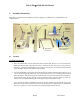
Lift-O-Flex 17000 SP 400 Manual 2. Assembly instructions Each lifter is to be delivered in modules and will be shipped in cardboard box(s). Components are as indicated below. Leg-RH Leg-LH Lift Mast Intermediate Section Handlebar w/Remote Controller Brake Rod 2.1 End-Effector Fixed Forks Electronic Power Pack with ground cable attached Assembly Assembly instructions 1. Place the intermediate section without lift motor attached and stand it on its end on the floor.
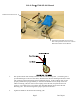
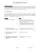
Lift-O-Flex 17000 SP 400 Manual Bolted Intermediate Section Lift Motor Intermediate Section-Lock in Place with Quick Disconnect Pin Located on Bolted Intermediate Section Bracket. 3. Pick up the lift mast and carefully insert the mast onto the mounting slide. (A mounting slot is provided full length on the rear of the mast). Slide the mast onto the mounting slide until it mates with coupling located at the bottom of the intermediate section.
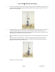
Lift-O-Flex 17000 SP 400 Manual 5. Take the power package and let it slide into the slot on the rear of the lift mast. Then lower it until it stops just above the mast mounting yoke and tighten the handle. Plug the motor cable into its outlet on the power package. 6. Take the handle and let it slide into the slot on the backside of the lift mast and lock it in place at a comfortable height. Make sure that the remote control holder is placed on the handle in an adequate position.
Lift-O-Flex 17000 SP 400 Manual Disposal after useful life When the lifter has provided many years of use and is ready to be disposed of, it should be recycled. The LIFT-O-FLEX lifter is manufactured with materials that are recyclable. We have also selected recyclable gel-cell batteries over nickel-cadmium batteries for this purpose. 3. Operating instructions 3.1 Operating In order to prevent and avoid work injuries it is important that the LIFT-O-FLEX be operated in a proper manner. 3.1.
Lift-O-Flex 17000 SP 400 Manual 3.1.2 Handlebar The height of the handlebar can easily be adjusted by loosening the quick disconnect handles and sliding the handlebar to the desired position. After adjustment, tighten the quick disconnect handles. To obtain the best working conditions it is important to adjust the handle to a comfortable level. During movement of the lifter, always keep hands inside the handle. This will protect the hands if the handlebar should encounter an obstacle. 3.1.
Lift-O-Flex 17000 SP 400 Manual Directional wheel locks When moving a heavy load, it is both easier and safer if you use the directional wheel locks by moving the red bar into the upper position. Both back wheels are now locked in a straightforward position. This gives greater directional stability when moving heavy loads. Observe that it is especially important that a heavy load be kept as low and as centered on the end-effector as possible. 3.
Lift-O-Flex 17000 SP 400 Manual 3.3 Maintenance Regular maintenance is important to protect the continued use of the LIFT-O-FLEX lifter. Daily maintenance 1. Wash the lifter with a detergent suitable for powder coat surfaces, aluminium and stainless steel. Follow the instructions on the detergent. Wipe the lifter dry. Do not use a high-pressure hose. It could damage both the electronics as well as the chassis. 3.
Lift-O-Flex 17000 SP 400 Manual 4. Enclosures 4.1 Electrical wiring 4.1.
Lift-O-Flex 17000 SP 400 Manual 4.1.
Lift-O-Flex 17000 SP 400 Manual 4.3.
Lift-O-Flex 17000 SP 400 Manual 4.3.4 Intermediate Section Part No. 30-0071 Item No. Qty 1 2 3 4 5 6 7 8 9 10 11 12 13 14 15 16 17 18 19 20 21 22 23 24 25 26 1 1 3 2 1 1 1 1 1 1 1 1 3 1 1 6 1 3 3 1 1 1 1 1 1 1 Part No. Description Front Beam SS Motor Cover Screw Screw Motor 403-930 Wedge 3 x 3.7 Bowex Junior 14 Stop Screw Fitting PG 13.5 Cable 4x1.5 Shielded Bracket-Brake Stop Screw Wedge 3x2.5 Driving Disc for Brake Screw Washer Screw Washer Fitting PG 13.
Lift-O-Flex 17000 SP 400 Manual 8 4.3.5 Legs 4 1 6 2 5 3 10 9 Part No. 14016-10 Item No. 1 2 3 4 5 6 7 8 9 10 Qty 1 1 2 2 4 1 4 2 2 2 Description Part No. Leg Left Leg Right Swivel Caster – Front – Dual Wheel-75mm Screw Screw Washer Washer Cap Rear Wheel –100mm - ESD Swivel Assembly-Rear w/Brake Rod Socket Page 15 HP0009L HP0009R 19502 MF6S M12x30 10.9 fxb K62 M8x12 10.9 fzb LM6M M12 1Z 8.
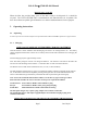
Lift-O-Flex 17000 SP 400 Manual 4.4.6 Mast Part No. 15700E03 Item No. Qty Description 1 2 3 4 5 6 7 8 9 10 11 12 13 14 15 16 17 18 19 20 21 22 23 24 1 1 1 1 1 1 1 1 4 4 1 1 1 4 19 1 1 1 2 1 1 1 1 1 Key Slide Coupling Sleeve Ball Bearing Pillow Block Bearing Ball Screw Ball Nut Stop Screw Shaft Wheel Slide Stop Screw End Cover Screw Spring Washer Bowex Junior 14 Mast Profile Spring Mast Brush Nut Screw Connecting Unit Spacer L=15 Spacer L=5 Washer Part No.
Lift-O-Flex 17000 SP 400 Manual 4.4.7 Handle Part No. 17280HP Item No. 1 2 3 4 5 6 Qty 1 1 1 2 2 2 Description Handle Remote Control Holder Lock Bar Knob Washer Handlebar Grips Page 17 Part No. 17280-01 17201 19134 17256 BRB 8.
Lift-O-Flex 17000 SP 400 Manual 4.4.
Lift-O-Flex 17000 SP 400 Manual Part No. 17287 Item No. 1 4.4.9 Qty 1 Description Brake Rod Part No. 174287 Power Pack Note: Ground Cable with alligator clip not shown Part No. 15700E04 Item No. 1 2 3 4 5 6 7 8 9 Qty 1 1 1 4 2 5 2 2 1 Description Power Pack Cover Battery 6V Battery 12V Screw Handle Screw Screw Bar Washer Control Board BG6 18V Page 19 Part No.
Lift-O-Flex 17000 SP 400 Manual 10 11 12 13 14 1 1 1 1 2 Charger Plug Base Insert Cable Kit Screw 17327 RonI Supplied RonI Supplied 17126 4.4.10 Lifter Check List During assembly of the LIFT-O-FLEX 17000 SP 400 components are required to be inspected prior to using the lifter. This is to ensure that the lifter will operate safely and ergonomically. Casters swivel and rotate properly Intermediate section assembled to legs with the bolts provided and are secure.
Lift-O-Flex 17000 SP 400 Manual 5. Declaration of Conformity Referring to Directive for machines 89/392/EEC with addendum - appendix 2A Supplier: RONI,LLC,9311 Monroe Rd, Suite D, Charlotte, NC 28270 Address Description: LIFT-O-FLEX® 17000 SP 400 Regulations: AFS 1993:10 (89/392/EEG) AND (91/368/EEG) Regulations that the lifter complies to. Standards: (when applicable) EN 292-1, EN 292-2, EN 294, EN 60204-1, EN 349 Applicable harmonized standards IKH 4.30.