HP Integrity Superdome 2 User Service Guide Abstract This document contains specific information that is intended for users of this HP product.
© Copyright 2010 - 2013 Hewlett-Packard Development Company, L.P. Trademark Acknowledgements Intel and Itanium are trademarks of Intel Corporation or its subsidiaries in the in the U.S. and other countries. "Genie" is a registered trademark of Genie Industries in the USA and many other countries. Warranty To obtain a copy of the warranty for this product, see the warranty information website: http://bizsupport2.austin.hp.com/bc/docs/support/SupportManual/c01865770/c01865770.pdf.
Contents 1 HP Integrity Superdome 2 system overview....................................................6 Complex components................................................................................................................6 Power subsystem.......................................................................................................................6 Manageability subsystem...........................................................................................................
Cooling errors...................................................................................................................45 Location errors...................................................................................................................45 Configuration errors...........................................................................................................45 Device failure errors................................................................................................
Remotely accessing the Onboard Administrator.................................................................79 Locally accessing the Onboard Administrator....................................................................80 Troubleshooting processors......................................................................................................81 Processor module behaviors................................................................................................81 Firmware......................
1 HP Integrity Superdome 2 system overview The HP Integrity Superdome 2 is a blade-based, high-end server platform supporting the Intel Itanium 9300 and 9500 processor family. Superdome 2 incorporates a modular design to enable increased scalability through the addition of server blades and external I/O enclosures. Superdome 2 complexes use the sx3000 crossbar fabric to interconnect CPU, memory and I/O resources into hard (nPartition) and/or virtual (vPar) partitions.
Superdome 2 IOX enclosures support two ac power supplies with a minimum of one power supply required to provide all necessary power to the enclosure and two power supplies providing 2N redundancy. Manageability subsystem Superdome 2 is managed by two Superdome 2 OAs that monitor both individual complex components and complex health. This information can be accessed one of two ways: • A GUI using a remote terminal. • A CLI using a remote or local terminal.
I/O expansion enclosure HP Integrity Superdome 2 complexes support up to eight IOX enclosures (four in SD2-8s complexes) to provide additional I/O for server blades through Superdome 2 crossbar fabric cables from the XFMs in the compute enclosure to IOX enclosures. In addition, CAMnet interconnection is provided through standard CAT6 cables from the GPSMs to the IOX enclosures. An IOX contains two I/O bays each supporting up to six PCIe cards (for a total of 12 PCIe cards per IOX).
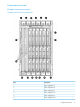
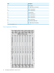
Component overview Compute enclosure overview Compute enclosure front components Item Description 1 Power supply bay 7 2 Power supply bay 8 3 Power supply bay 9 4 Power supply bay 10 5 Power supply bay 11 6 Power supply bay 12 Component overview 9
Item Description 7 DVD module 8 Air intake slot (Do not block) 9 Power supply bay 6 10 Power supply bay 5 11 Insight Display 12 Power supply bay 4 13 Power supply bay 3 14 Power supply bay 2 15 Power supply bay 1 16 Superdome 2 Blade slots1 17 Air intake slot (Do not block) 1 For more information, see “Server Blade slot numbering” (page 11).
Server Blade slot numbering IMPORTANT: When looking at the rear of the enclosure, Blade slot numbering is reversed.
HP Integrity Superdome 2 Insight Display components 12 Item Description Function 1 Insight Display screen Displays Main Menu error messages and instructions 2 Left arrow button Moves the menu or navigation bar selection left one position 3 Right arrow button Moves the menu or navigation bar selection right one position 4 OK button Accepts the highlighted selection and navigates to the selected menu 5 Down arrow button Moves the menu selection down one position 6 Up arrow button Moves t
Compute enclosure rear components Item Description 1 ac power connectors (upper) 2 Fan bay 1 3 Fan bay 6 4 Fan bay 2 5 Fan bay 7 6 Fan bay 3 7 Fan bay 8 8 Fan bay 4 9 Fan bay 9 Component overview 13
Item Description 10 Fan bay 5 11 Fan bay 10 12 Power supply exhaust vent (Do not block) 13 XFM bay 1 14 XFM bay 2 15 XFM bay 3 16 XFM bay 4 17 GPSM bay 2 18 Interconnect bay 2 19 Interconnect bay 4 20 Interconnect bay 6 21 Interconnect bay 8 22 Onboard Administrator bay 2 23 Power supply exhaust vent (Do not block) 24 ac power connectors (lower) 25 Fan bay 15 26 Fan bay 14 27 Fan bay 13 28 Fan bay 12 29 Fan bay 11 30 Onboard Administrator bay 1 31 Interconnec
Fan bay numbering Interconnect bay numbering Each compute enclosure requires interconnect modules or IOX enclosures to provide network access for data transfer. Interconnect modules reside in bays located in the rear of the enclosure. Be sure to review Blade slot numbering to determine which external network connections on the interconnect modules are active. The IOX enclosures are external and connected to the XFMs in compute enclosures through Superdome 2 crossbar fabric cables.
To support network connections for specific signals, install an interconnect module in the bay corresponding to the embedded NIC or mezzanine signals. Server blade signal Compute enclosure interconnect bay Interconnect bay labels NIC 1 (Embedded) 1 NIC 2 (Embedded) 2 NIC 3 (Embedded) 1 NIC 4 (Embedded) 2 NOTE: For information on the location of LEDs and ports on individual interconnect modules, see the documentation that ships with the interconnect module.
Server blade overview Server blade components Item Description 1 CPU 1 socket power connector 2 CPU 1 socket 3 Agent baffle 4 Agent ASIC 1 5 Agent ASIC 0 6 Center air baffle 7 Battery sockets (PDH battery on left, iLO Battery on right) 8 IOH ASIC 9 CPU 0 socket 10 Lower air baffle 11 CPU 0 socket power connector 12 DDR3 DIMM slots (32) 13 SUV connector 14 Server blade release levers (2) 15 Server blade release buttons (2) 16 Serial label pull tab 17 SUV board Component o
SUV cable and ports The SUV port on the front of the server blade is used with an SUV cable to connect the blade to external devices such as a terminal emulator or monitor. CAUTION: The SUV cable is not designed to be used as a permanent connection, be careful when walking near the server blade. Hitting or bumping the cable might cause the port on the server blade to break and damage the system board. IMPORTANT: 18 The SUV port does not provide console access.
IOX enclosure overview IOX enclosure components Item Description 1 I/O bay 2 OL* board 2 Power supplies (2) 3 I/O bay 1OL* board 4 PCIe slot release latches (12) 5 PCIe card slots (12) 6 SAS battery location 7 Fan 4 8 Fan 3 9 I/O backplane release lever 10 Fan 2 11 Fan 1 12 SAS battery location Component overview 19
Item Description 13 ac transfer boards (2) 14 PSU tunnel HP Integrity Superdome 2 system overview
2 System specifications Dimensions and weights Component dimensions Table 1 Component dimensions Component Width (in/cm) Depth (in/cm) Height (in/cm) Compute enclosure 17.6/44.7 32.6/82.8 31.4/79.8 Server blade 2.02/5.13 19.69/50.01 24.48/62.18 I/O expansion enclosure 17.2/43.7 22.5/57.2 6.8/17.3 Component weights Table 2 Compute enclosure weights Component Weight (lb/kg) Max quantity per enclosure Compute enclosure chassis 143.0/64.9 1 I/O chassis2 48.7/22.1 1 Midplane Brick 41.
Rack specifications Table 4 Compute enclosure weights Total cabinet area with packing materials (HxDxW) U height Width Depth Dynamic load (gross) Static load HP 10642 G2 219 x 121.92 x 90.3 cm (86.22 x 48 x 35.56 in) 42U 600 mm (23.8 in) 1,000 mm (47.2 in) 907.2 kg (2,000 lb) 1,360.8 kg (3,000 lb) HP 10636 G2 36U 600 mm (23.6 in) Universal Rack 191.14 x 121.92 x 81.28 cm (75.25 x 48 x 32 in 36U 600 mm (23.8 in) 1,000 mm (39.4 in) 689.5 kg (1,520 lb) 907.
Electrical specifications Table 5 Compute enclosure power options Source type 3–phase Source voltage (nominal) Plug or connector type 200–220 VAC line-to-line (phase-to-phase), 3–phase NEMA L15-30p, 30A 3-phase 3-Pole, 4-wire, 3m (10ft) power cord Circuit type Power receptacle required Number of power cords required (per enclosure) L15-30R.
Table 8 Compute enclosure 3-phase HP 2400 W power supply specifications (North America/Japan) (continued) Specification Value 3.0m (10ft) Max input current per line cord 24.0 A at 200 VAC 23.1 A at 208 VAC Input requirements Rated input voltage 200 VAC to 240 VAC line-to-line 3–phase Rated input frequency 50–60 Hz Maximum inrush current 100 A for 10 ms Ground leakage current 3.5 mA Power factor correction 0.
Table 11 Compute enclosure PDU power options Number of power cords required (per enclosure leaving the rack) Source voltage (nominal) Power receptacle Plug or connector type required 200–220 VAC line-to-line (phase-to-phase), 3–phase IEC 309 60A 3-Pole, 4 wire, Blue, 3.6m (11.8ft) power cord IEC 309 60A 3-Pole, 4 wire, Blue 2 3–phase 32A 220 VAC to 240 VAC IEC 309 32A 4-Pole, line-to-neutral 3–phase 5 wire, Red, 3.6m (11.
Table 14 IOX enclosure power requirements Power Required (50–60 Hz) Watts VA User Expected Maximum Power1 525 535 1 Typical maximum power or User expected maximum power (Input power at the ac input expressed in Watts and Volt-Amps.) This figure is developed with the absolute maximum configuration running applications designed to draw the maximum power possible. It is highly unlikely that any real-world application will result in this amount of power use for any significant time period.
HP Integrity Superdome 2 utilizes variable speed fans to realize the most efficient use of air. The volume of air required varies with the temperature of the air supplied to the inlet of HP Integrity Superdome 2. The following table and chart illustrate the necessary volume of air to enable proper operation. IMPORTANT: Equipment orientation will best be served in a parallel fashion to the air flow supply and return.
NOTE: While this chart shows airflow volumes for temperatures exceeding the specified inlet air temperature maximum of 32° C, proper operation above this point is not guaranteed. Because the airflow/watt is quite low for Superdome 2, the exhaust air temperature is, by design, quite high. The following is a chart that shows exhaust air temperature versus inlet air temperature.
Because these temperatures might be significantly higher than the temperatures of the other equipment in the data center, to not over-cool the air, you might have to adjust the set-points of the CRACs or CRAHs higher. Most standalone CRACs and CRAHs use return side temperature regulation rather than supply side.
You must understand the acoustic noise specifications relative to operator positions within the computer room when adding HP Integrity Superdome 2 systems to computer rooms with existing noise sources. For more information about general site preparation guidelines, see the Generic Site Preparation Guide. Sample Site Inspection Checklist for Site Preparation See Table 16 (page 30) and Table 17 (page 30). You can use these tables to measure your progress.
Table 17 Site Inspection Checklist (continued) Check either Yes or No. If No, include comment number or date. 11. Are floor tiles in good condition and properly braced? 12. Is floor tile underside shiny or painted? If painted, judge the need for particulate test. Comment or Date Power and Lighting Number Area or Condition 13. Are lighting levels adequate for maintenance? 14. Are ac outlets available for servicing needs (for example, laptop)? 15.
Table 17 Site Inspection Checklist (continued) Check either Yes or No. If No, include comment number or date. Comment or Date Training Number Area or Condition 33. Are personnel enrolled in the System Administrator’s Course? 34. Is on site training required? For more information about general site preparation guidelines, see the Generic Site Preparation Guide.
3 HP Integrity Superdome 2 Insight Display Insight Display overview The Insight Display enables the rack technician to initially configure the enclosure. It also provides information about the health and operation of the enclosure. The color of the Insight Display varies with the condition of the enclosure health: • Blue— The Insight Display illuminates blue when the enclosure UID is active.
1. Review each setting on the Enclosure Settings screen for accuracy. To change any value, navigate the cursor to the menu option to be edited, and press the OK button. 2. Change the setting to the appropriate value, navigate the cursor to Accept, and then press the OK button to return to the Enclosure Settings menu. Repeat this step until all options on the Enclosure Settings menu are accurate. TIP: Select the ? icon to access detailed help information about each setting or topic.
NOTE: When calculating the Power Limit Watts ac value, derate the circuit to 80% of the maximum to prevent tripping the circuit breaker (United States only). NOTE: If your facility cannot support the calculated peak Watts ac, set the Power Watts ac value to match the capability of your facility. • Dynamic Power —The default setting is Enabled.
5. ◦ Detach/Attach—Each blade can be individually attached to or detached from the enclosure DVD drive by navigating to that bay and pressing the OK button. ◦ Change—Navigates to the Attach:Enclosure DVD menu where you can attach, attach and reboot, or detach all bays from the DVD drive. ◦ Navigate to the DVD icon for a blade and press the OK button to change the settings for an individual server. ◦ Navigate to All Blades and then press OK to change the settings for all servers in the enclosure.
7. If no errors are detected, the rear enclosure UID turns off, and the Insight Display screen illuminates green. Press the OK button to return to the Main Menu. Enclosure and blade hardware setup and configuration is complete. If errors are detected, then the Insight Display screen glows amber, and the Health Summary screen appears. For more information on troubleshooting, see “Insight Display errors” (page 44).
The Main Menu of the Insight Display has the following menu options: • Health Summary • Enclosure Settings • Enclosure Info • Blade or Port Info • Turn Enclosure UID on/off • View User Note • Chat Mode If the active Onboard Administrator detects a USB key drive with any *.ROM , *.CFG or *.ISO files, a USB menu item appears at the bottom of the Main Menu. If the active Onboard Administrator detects KVM capability, a KVM menu button appears on the navigation bar of the Main Menu.
TIP: Within any menu option, navigate the cursor to What is This, and press the OK button to view additional information about each setting, option, or alert.
NOTE: A black DVD rectangle indicates no DVD drive is connected to the Onboard Administrator while a dark gray rectangle indicates the DVD drive is present, but that no media is present. A dark green rectangle indicates that media is present, but not actively connected to any server or that all connected servers have issued a disk eject command, so the disk can be removed from the drive.
TIP: Set a PIN to protect the enclosure settings from changes. Navigate the cursor to a setting or to ?, and press OK to change the setting or get help on that setting.
Blade and Port Info screen The Blade and Port Info screen displays information about a specific server blade. On the first screen, select the server blade number, and then press the OK button. Select Blade Info or Port Info, and press the OK button. To view information about the server blade, select Blade Info and press the OK button. To view the ports used by a specific server blade, select Port Info and press the OK button. The following screen shows a server blade with four embedded NICs.
Turn Enclosure UID On/Off screen The Main Menu displays Turn Enclosure UID Off when the enclosure UID is active, and displays Turn Enclosure UID on when the enclosure UID is off. Selecting Turn Enclosure UID On from the main menu turns on the rear enclosure UID LED and changes the color of the Insight Display screen to blue. Selecting Turn Enclosure UID Off from the main menu turns off the rear enclosure UID LED and changes the color of the Insight Display screen to the current alert condition.
Chat Mode screen The Chat Mode screen is used by the remote administrator who uses the web interface to send a message to an enclosure Insight Display. The technician uses the Insight Display buttons to select from a set of prepared responses, or dials in a custom response message on the ? line. To send a response back to the Administrator, navigate the cursor to Send, then press the OK button. The Chat Mode screen has top priority in the Insight Display and remains on the screen until you select Send .
When the enclosure UID LED is off, the Insight Display is illuminated amber when any error condition exists.
Device failure errors Device failure errors occur when a component has failed. Device failure errors can occur on all components, including: • Server blades • Storage blades • Power supplies • Interconnect modules • Onboard Administrator modules • Fans • ac power inputs To correct a device failure error: 1. Use the arrow buttons to navigate to Fix This, and press OK. 2. Review and complete the corrective action suggested by the Insight Display.
4 Booting and shutting down the operating system Operating systems supported on the server blade • HP-UX 11i v3 HWE 1009 Booting and shutting down the operating system for HP-UX HP-UX standard boot Use either of the following procedures to boot HP-UX: • “Booting HP-UX from the UEFI Boot Manager” (page 47) • “Booting HP-UX from the UEFI Shell” (page 47) Booting HP-UX from the UEFI Boot Manager From the UEFI Boot Manager menu, choose an item from the boot options list to boot HP-UX. 1.
Booting HP-UX in single-user mode 1. 2. Use steps 1–5 from “Booting HP-UX from the UEFI Shell” (page 47) to access the UEFI shell and launch the HPUX.EFI loader. Access the HP-UX Boot Loader prompt (HPUX>) by pressing any key within the 10 seconds given for interrupting the HP-UX boot process. Use the HPUX.EFI loader to boot HP-UX in single-user mode in the next step. After you press a key, the HPUX.EFI interface (the HP-UX Boot Loader prompt, HPUX>) launches. For help using the HPUX.
5 Troubleshooting The purpose of this chapter is to provide a preferred methodology (strategies and procedures) and tools for troubleshooting complex error and fault conditions. Methodology General troubleshooting methodology The system provides several sources of information for troubleshooting: • LED status information • Front door display/insight display • The OA CLI • The OA GUI LED status information The LEDs provide initial status and health information.
Gathering power related information (overview) Gather the power information for all of the system components. Compute enclosure (enclosure 1 and enclosure 2 – if present) Use the show enclosure status and show enclosure powersupply all commands.
Diagnostic Status: Internal Data Device Failure Power Cord Indicted OK OK OK OK Similar information will be displayed for all other power supplies. Collecting power status information for components at the compute enclosure Use the show xfm status all, show blade status all, and show interconnect status all commands to gather information on compute enclosure component power: NOTE: Similar information should be displayed for XFMs 2 through 4.
UID: Off Powered: On Diagnostic Status: Internal Data Management Processor Thermal Warning Thermal Danger I/O Configuration Power Device Failure Device Degraded OK OK OK OK OK OK <<< OK OK IOX enclosures Use the show IOX power all command to gather information on IOX enclosure power: sd-oa1> show iox power all IOX 5: No IOX Installed IOX 6: No IOX Installed IOX 7: No IOX Installed IOX 8: No IOX Installed IOX 9: Present Power: 189 Watts AC IOX 10: Present Power: 222 Watts AC IOX 11: No IOX Installed IOX 1
Missing Device Indicted • OK OK show blade status all sd-oa1> show blade status all Blade #1 Status: Power: On Current Wattage used: 1325 Watts Health: OK Unit Identification LED: Off Diagnostic Status: Internal Data OK Management Processor OK Thermal Warning OK <<<< Thermal Danger OK <<<< I/O Configuration OK Power OK Cooling OK <<<< Device Failure OK Device Degraded OK Device Info OK Firmware Mismatch OK PDHC OK Indicted OK • show xfm status all Bay 4 XFM Status: Health: OK Power: On Unit Identificat
Power Device Failure Device Degraded OK OK OK Gathering failure information (overview) To obtain information about failures recorded by the system, use the following commands: • Show cae –L (within HR, run show HR to enter the HR submenu) sd-oa1> show cae -L Sl.No Severity EventId EventCategory PartitionId EventTime Summary ################################################################################ 71 Critical temperatur... 70 Critical temperatur... • 3040 System Coo...
Event Subcategory : Unknown Probable Cause : Temperature Unacceptable Event Threshold : 1 Event Time Window (in minutes): 0 Actual Event Threshold : 1 Actual Event Time Window (in minutes): 0 OEM System Model : NA Original Product Number : AH337A Current Product Number : AH337A OEM Serial Number : NA Version Info : Complex FW Version : 2.52.2 Provider Version : 3.
Item Name Description 1 UID LED Blue = UID on 2 Health LED Green = OK Flashing yellow = Degraded Flashing red = Critical error 3 NIC LED 1 Indicates the status of the NIC. Solid green = Network linked, no activity Flashing green = Network linked, activity 4 NIC LED 2 Indicates the status of the NIC. Solid green = Network linked, no activity Flashing green = Network linked, activity 5 NIC LED 3 Indicates the status of the NIC.
Item Name Description 7 Power LED Indicates if the server blade is powered on and active. Green = Powered on and active Flashing yellow = Powered on, not active 8 SUV connector Power supply LEDs NOTE: The power supplies at the top of the enclosure are upside down.
Fan LED LED color Fan status Solid green The fan is working. Solid amber The fan has failed. Flashing amber See the Insight Display screen.
XFM LEDs and components Item Name Description 1 UID LED Blue = UID on 2 Power LED Indicates if the module is powered on.
Item Name Description Off = Ok Flashing red = Deconfigured 1 Solid green = Link OK, transmitting at full bandwidth. Alternating green/yellow = Link in service, safe to remove. Flashing yellow = Deconfigured link, safe to remove. CAUTION: Always use the HR user interface stop link command before disconnecting the Superdome 2 crossbar fabric cable. The stop link will allow safe servicing and set the LED endpoints for easy location.
Item Name Description Flashing yellow = Critical error 13 External Clock Input LED Indicates the status of the global clock signal distributed to connected enclosures.
IOX LEDs and components IOX enclosure front Item Name 1 Serial label pull tab 2 Rack release latch (2) 3 Power LED Description Indicates if the IOX enclosure is powered on. Green = On 4 Health LED Green = OK Flashing yellow = Degraded Flashing red = Critical error 5 UID LED Blue = UID on Each CAMNet connector has a Link LED and an Activity LED.
IOX enclosure rear Item Name Description 1 Link Cable Status LEDs Indicates the status of the Xbar Fabric link. Solid green = Link OK, transmitting at full bandwidth Alternating green/yellow = Link in service, safe to remove. Flashing yellow = Deconfigured link, safe to remove. CAUTION: Always use the HR user interface stop link command before disconnecting the Superdome 2 crossbar fabric cable. The stop link command will allow safe servicing and set the LED endpoints for easy location.
PCIe slot LEDs and components Item Name 1 Attention LED 2 Power LED 3 PCIe Hot Plug button 4 Slot release latch Each PCIe slot has two LEDs that indicate the status of the PCIe slot: Power LED Attention LED Status Off Off Slot is powered off Green Off Slot is powered on and normal Green Flashing yellow Slot is powering down CAUTION: card.
HP Integrity Superdome 2 Onboard Administrator module LEDs and components Item Name Description 1 Reset button — 2 OA management LAN port Standard CAT5e (RJ-45) Ethernet port (100/1000Mb) which provides access to Superdome 2's management subsystem. Access to the OA's CLI and GUI interfaces, interconnect modules, and iLO features, such as vMedia, require connection to this port.
DVD module LEDs and components Item Name 1 USB connector 2 DVD tray 3 DVD activity LED 4 Tray open/close button 5 Manual tray release 6 Health LED Description Green = OK Flashing yellow = Critical error 7 UID LED Blue = UID on OA GUI The OA GUI provides partition status and FRU information. For more information on using the OA GUI, see the HP Integrity Superdome 2 Onboard Administrator User Guide. NOTE: CAE events and errdump information is not available using the GUI.
No status | Firmware Information Normal | Memory Normal | Management Processor No status | Partition Information No status | Memory Utilization No status | Process Information No status | Boot Device Configuration No status | Crash Dump Configuration Normal | FC HBA Normal | IOTree Minor | Network Information **************************************** # • # cprop -summary -c component – Displays summary information for all the instances of all the components.
. . [Component]: Processors ------------------------------------------------------[Instance]: 1 **************************************************** [Hash ID]: Processors:b67cbfdcx3041aa68 [Test Name]: HP:CpuDiag [Job ID]: 20120713105142-0 [Status]: Complete **************************************************** [Instance]: 2 **************************************************** Health Repository viewer The Health Repository User Interface displays the information from the HR database.
well. For example, DIMMs and CPU sockets on an inserted blade will be acquitted. Any deconfigurations will be reversed. • AC power cycle or CLI poweron xfabric command — HR will assume that the required service has been accomplished for the entire complex. All FRUs and sub-FRUs will be acquitted and reconfigured. • Cohort acquittal — When analysis of a single fault event results in indictment or suspicion records against multiple components, the records are linked together.
Requested Deconfig State: Configured Current Deconfig State: Configured FRU Type: CPU Socket Location: 0x0100FF01FF00FF11 enclosure1/blade1/socket0 Timestamp: Mon May 18 16:05:57 2009 Indictment State: Indicted Requested Deconfig State: Configured Current Deconfig State: Configured --- end report --- 2 records shown Viewing deconfigured components The show deconfig will list all components in the complex which are deconfigured or have a pending request to be deconfigured.
FRU Type: CPU Socket Location: 0x0100FF01FF00FF11 enclosure1/blade1/socket0 Timestamp: Mon May 18 16:11:19 2009 Indictment State: Acquitted Requested Deconfig State: Configured Current Deconfig State: Deconfigured --- end report --- 2 records shown NOTE: The requested and current deconfiguration states shown in the examples above are not the same. This can happen when requested deconfiguration changes are not be acted on until the n-Par containing the component in question is rebooted.
- SubFru Isolation SubFRUs requiring service shown here. If none, section omitted. - SubFru Deconfiguration Deconfig’ed subFRUs shown here. If none, section omitted. - Related Locations 0x0B00FFFF03FFFF54 (Cohorts. If none, section omitted.) Subcomponent isolation and deconfiguration displays Subcomponent isolation refers to the subcomponents of a part that can require service.
The log can be filtered using the following items: • blade number • partition number • alert level The following format options are also available: • • Keyword – This is the default format for all viewers.
Alert filter will cause events at the selected alert filter and below to be shown 0: Minor Forward Progress 1: Major Forward Progress 2: Informational 3: Warning 5: Critical 7: Fatal The following event filter options are available: B: Blade P: Partition V: Virtual Partition U: Unfiltered Current alert threshold: Alert threshold 0 Current filter option: Unfiltered Current format option: Extended Keyword Select new filter/format option, or to exit or to resume display of live events, or H/? for
• ◦ hexadecimal dump of event records ◦ event ID keyword Raw hex – The raw hex format supplies following information about an event: ◦ • • hexadecimal dump of event records Text – The text format supplies the following information about an event: ◦ log number ◦ timestamp ◦ alert level ◦ event ID keyword ◦ brief text description ◦ reporting entity type ◦ reporting entity ID ◦ hexadecimal dump of event records Problem/Cause/Action - The Problem/Cause/Action format displays the proble
Current filter option: Unfiltered Current format option: Extended Keyword MP:VWR (,,+,-,?,H,C,F,I,L,J,D,K,E,R,T,B,P,V,U,/,\,N,0,1,2,3,5,7,) > Location: Enclosure, Device Bay, Socket, Core, Thread AL Encoded Field AL: Alert Level Event# Rep Ent Location nPar: vPar 848 847 846 845 844 844 843 843 842 842 841 841 840 840 839 839 838 838 837 836 835 834 SFW SFW SFW SFW OA 1,1,0,0,0 1,1,0,0,0 1,1,0,0,0 1,1,0,0,0 1,1 255:255 255:255 255:255 255:255 1 0 0 0 0 1 OA 1,1 1 0 1680264000e1
18 18 17 17 16 16 15 15 14 14 13 13 12 12 11 11 OA 1,1 None PDHC 1,2 14:3 OA 1,1 ILO 1,1 None OA 1,1 None OA 1,1 1 OA 1,1 None ILO 1,1 None None 2 4480201f00e10023 0100ff01ffffff94 OA_HWMGR_DAEMON_BLADE_POWER_ON_SUCCESS 04/24/2012 06:27:51 2 438028d300e10021 0000000000000150 BLADE_DIMM_VOLTAGE 04/24/2012 06:27:49 2 4480201d00e1001f 0100ff01ffffff94 OA_HWMGR_DAEMON_BLADE_POWER_ON_CONTINUE 04/24/2012 06:27:49 2 4b00260300e1001e 010000004f96aa53 OA_REQUESTS_POWER_CHANGE 04/24/2012 06:2
2.
Recommended Action 1 : Check the XFabric links. The FRU's used to implement the link that caused the MCA is included as a reference. Check for physical damage on the FRU connection points and ensure proper mating/seating occurs. Check the system error logs for other events describing previous XFabric link failures. If the problem persists, replace only one FRU at a time in the order given below. Test the system between each FRU replacement Replaceable Unit(s) : Part Manufacturer Spare Part No.
2. At the prompt, enter telnet and then press Enter. For example, telnet 192.168.100.130. 3. 4. 5. 6. Enter a valid user name and press Enter. Enter a valid password and press Enter. The CLI command prompt appears. Enter commands for the Onboard Administrator. To end the remote access telnet session, at the CLI command prompt, enter Exit, Logout, or Quit. Procedure 2 SSH session 1. 2. 3. 4. 5. 6. Using any SSH client application, start a SSH session to the Onboard Administrator.
3. 4. 5. 6. Parameter Value Parity None Stop bits 1 Protocol None When prompted, enter a valid user name, and then press Enter. Enter a valid password, and then press Enter. The CLI command prompt appears. Enter commands for the Onboard Administrator. To end the terminal session, enter Exit at the prompt. NOTE: If the serial session is not closed properly using the exit command, it can cause the console to respond slowly.
System firmware can be updated if the complex is already running firmware bundle 2.2.27 or higher. For any firmware bundle release of 1.x.y a complex outage is required. System firmware will be updated through the OA (either a USB key is inserted in the USB slot at the DVD assembly or using an FTP server ). IMPORTANT: Always use the all option when updating firmware on a SD2 system. For example: OA1> update firmware usb://d2/hpsd2-2.xx.xxx-fw.
3. 4. 5. Select your product. Select your operating system or Cross operating system (BIOS, Firmware, Diagnostics, etc.). This takes you to the product download page. Select the appropriate download, and follow the instructions. NOTE: If the Superdome 2 system already has firmware bundle 2.2.27 or later installed, then it is possible to update firmware without taking all the partitions down at once.
EBIPA Settings - Device Bay iLO Processors Domain: Subnet Mask: 255.255.255.0 DNS Server1: 0.0.0.0 Server3: 0.0.0.0 Gateway: 172.22.aaa.bbb Server2: 0.0.0.0 Bay Enabled EBIPA Address Current Address --- ------- --------------- --------------1 Yes 172.22.a.b 172.22.a.b 1A No N/A 1B No N/A 2 Yes 172.22.a.b 172.22.a.b . . SHOW OA NETWORK ALL Device Type -----------Server Blade [Absent] [Absent] Server Blade Onboard Administrator #1 Network Information: Name: OA-1 DHCP: Disabled IP Address: 172.22.aaa.
Test complete NOTE: The Test camnet command can be used on a single FRU while all partitions are running. Troubleshooting fabric issues The Superdome 2 system has fabric connections between the following major components: • Blade and XFM modules via enclosure upper backplane.
Clocks test started... Blade ========== Blade 1/1 Blade 1/2 Blade 1/3 Blade 1/4 Blade 1/5 Blade 1/6 Blade 1/7 Blade 1/8 Sys Clk 0 ========== OK OK OK OK OK OK OK OK Sys Clk 1 ========== OK OK OK OK OK OK OK OK GPSM ========== GPSM 1/1 * GPSM 1/2 * Int Clk ========== OK OK Ext Clk ========== ------- SUCCESS: Clocks test passed. Clocks test complete. Any clock failures will also be detected and reported by CAE.
Temperature sensors are found on: • I/O baseboard, where the processors provide an integrated temperature sensor. • Status panel, where a thermal sensor detects the ambient room temperature. This sensor reading is the main parameter used to regulate fan speed, under normal conditions. For detailed environmental specifications, see “Environmental specifications” (page 26).
6 Support and other resources Contacting HP Before you contact HP Be sure to have the following information available before you call contact HP: • Technical support registration number (if applicable) • Product serial number • Product model name and number • Product identification number • Applicable error message • Add-on boards or hardware • Third-party hardware or software • Operating system type and revision level HP contact information For the name of the nearest HP authorized reseller
Installing HP Insight Remote Support Software HP strongly recommends that you install HP Insight Remote Support software to complete the installation or upgrade of your product and to enable improved delivery of your HP Warranty, HP Care Pack Service or HP contractual support agreement.
User input Commands and other text that you type. Variable The name of a placeholder in a command, function, or other syntax display that you replace with an actual value. WARNING! A warning calls attention to important information that if not understood or followed will result in personal injury or nonrecoverable system issues. CAUTION: A caution calls attention to important information that if not understood or followed will result in data loss, data corruption, or damage to hardware or software.
A Utilities UEFI UEFI is an OS and platform-independent boot and preboot interface. UEFI resides between the OS and platform firmware, allowing the OS to boot without having details about the underlying hardware and firmware. UEFI supports boot devices, uses a flat memory model, and hides platform and firmware details from the OS. NOTE: Unified EFI Forum, Inc. defines the specification used to implement UEFI.
Table 19 UEFI Shell commands (continued) 92 UEFI Shell command Definition dblk Displays one or more blocks from a block device dbprofile Manages direct boot profiles default Sets default values devices Displays the list of devices managed by UEFI drivers devtree Displays the UEFI Driver Model-compliant device tree dh Displays UEFI handle information disconnect Disconnects one or more UEFI drivers from a device dmem Displays the contents of memory dmpstore Displays all UEFI NVRAM variabl
Table 19 UEFI Shell commands (continued) UEFI Shell command Definition mm Displays or modifies MEM/MMIO/IO/PCI/PCIE address space mode Displays or changes the console output device mode mount Mounts a file system on a block device mv Moves one or more files or directories to another location openinfo Displays the protocols and agents associated with a handle palproc Makes a PAL procedure call pause Prints a message and waits for keyboard input pci Displays PCI device list or PCI function co
• Boot From File • Set Boot Next Value • Set Time Out Value • Reset System Boot Options The Boot Options menu contains the following options: • Add Boot Option • Delete Boot Option • Change Boot Order Add Boot Option Use this option to add items to the Boot Options list.
1. Select a boot device type. 2. Use the File Explorer menu to locate the correct boot device. Delete Boot Option Use this option to delete boot options from the Boot Options list. NOTE: This does not delete any files, applications, or drivers from your server. To delete items from the boot list: 1. Press spacebar to toggle the check box for each boot option that you want to delete. 2. Select Commit Changes and Exit to save the new settings and return to the Boot Maintenance Manager.
To change the boot order: 1. Select an item on the boot order list. 2. Using the + and - keys, move the selection to the preferred position in the boot order list. 3. 4. Press Enter when the item is in the preferred position. Select Commit Changes and Exit to save the new settings and return to the Boot Maintenance Manager.
1. Select Add Driver Using File. 2. Use the File Explorer menu to locate the correct driver. Delete Driver Option Use this option to delete driver options. NOTE: This does not delete any files, applications, or drivers from your server. To delete driver options: 1. Press spacebar to toggle the check box for each driver that you want to delete. 2. Select Commit Changes and Exit to save the new settings and return to the Boot Maintenance Manager.
4. Select Commit Changes and Exit to save the new settings and return to the Boot Maintenance Manager. Console Options The Console Options menu is now disabled. Use the conconfig command from the UEFI Shell to set console options. Boot From File Use this option to manually run a specific application or driver. NOTE: This option boots the selected application or driver only once. When you exit the application, you return to this menu. 1. Select a boot device type. 2.
Set Time Out Value Use this option to set the duration for which the server pauses before attempting to launch the first item in the Boot Options list. Interrupting the timeout during the countdown stops the Boot Manager from loading any boot options automatically. If the countdown does not occur, boot options must be selected manually. To set the auto boot timeout value in seconds, select Set Timeout Value and enter the preferred value. Reset System Use this option to perform a system reset.
Access to the OA can be restricted by user accounts. User accounts are password protected and provide a specific level of access to the server (not OS) and OA CLI commands. For more information on the Onboard Administrator, see the HP Integrity Superdome 2 Onboard Administrator User Guide.
Standard terms, abbreviations, and acronyms A ASCII American standard code for information interchange. ASIC Application-specific integrated circuit. B BCH Boot console handler. C CPE Corrected platform errors. CRAC Computer room air conditioner. CRAH Compute room air handler. D DHCP Dynamic host configuration protocol. DNS Domain name system. E EFI Extensible firmware interface. See also UEFI. EIA Electronic Industries Association. ESD Electrostatic discharge.
POSSE Pre-OS system start-up environment. R RETMA Radio Electronics Television Manufacturers Association S SAL System abstraction layer. SDRAM Synchronous dynamic random access memory. SEL System event log. SIM System insight manager. SMBIOS System management BIOS. SSH Secure Shell. T TLB Translation look-aside buffer. ToC Transfer of control. U UEFI Unified extensible firmware interface, replaces EFI. UID Unit identification. UPS Uninterruptible power supply.
Index A E alerts Configuration errors, 45 Cooling errors, 45 Device failure errors, 46 Insight Display errors, 44 Location errors, 45 Power errors, 45 EFI see UEFI environmental specifications, 26 errors errors and error logs, 72 Insight Display, 44 B Blade slot numbering, 11 boot option add, 94 change boot order, 95 delete, 95 Set Boot Next Value, 98 boot option maintenance manager menu, 93 booting from file, 98 HP-UX (LVM maintenance mode), 48 HP-UX (UEFI boot manager), 47 HP-UX in single-blade mode,
L LEDs DVD module, 66 Enclosure UID, 58 fan, 58 GPSM, 60 Onboard Administrator, 58 XFM, 59 LEDs, power supply, 57 local access, 80 O Onboard Administrator, 99 local access, 80 remote access, 79 Onboard Administrator components HP Superdome 2 Onboard Administrator components, 65 overview I/O subsystem, 7 Insight Display, 12 manageability subsystem, 7 partitioning, 7 power subsystem, 6 rear components, 13 server blade, 7 system, 6 P PCIe slot LEDs, 64 power supply bay numbering, 10 power supply LEDs, 57 R