HP Installation Guide, HP Integrity Superdome/sx2000 and HP 9000 Superdome/sx2000 Servers HP Part Number: 5992-1042 Published: July 2011 Edition: 9
© Copyright 2006, 2011 Hewlett-Packard Development Company, L.P. The information contained herein is subject to change without notice. The only warranties for HP products and services are set forth in the express warranty statements accompanying such products and services. Nothing herein should be construed as constituting an additional warranty. HP shall not be liable for technical or editorial errors or omissions contained herein.
About This Document This document contains the installation procedures of the system and operating system specifics for components in the system. Intended Audience This document is intended for HP trained Customer Support Consultants. Document Organization This document is organized as follows: Chapter 1 This chapter describes how to unpack and inspect the system, set up the system, connect the MP to the customer LAN, and how to complete the installation.
Server Hardware Information The following website offers more information http://www.hp.com/go/integrity_servers-docs . It provides HP nPartition server hardware management information, including information on site preparation, installation, and more. Diagnostics and Event Monitoring: Hardware Support Tools The following link contains comprehensive information about HP hardware support tools, including online and offline diagnostics and event monitoring tools.
To contact HP by phone: ◦ Call 1-800-HP-INVENT (1-800-474-6836). This service is available 24 hours a day, 7 days a week. For continuous quality improvement, calls may be recorded or monitored. ◦ If you have purchased a Care Pack (service upgrade), call 1-800-633-3600. For more information about Care Packs, see the HP website: http://www.hp.com/hps. • In other locations, see the Contact HP worldwide (in English) website: http://welcome.hp.com/country/us/en/wwcontact.html.
1 Installing the System This chapter describes installation of HP Integrity Superdome/sx2000 and HP 9000/sx2000 systems. Installers must have received adequate training, be knowledgeable about the product, and have a good overall background in electronics and customer hardware installation. Introduction The instructions in this chapter are written for Customer Support Consultants (CSC) who are experienced at installing complex systems.
Public Telecommunications Network Connection Instructions are issued to the installation site that modems cannot be connected to public telecommunications networks until full datacomm licenses are received for the country of installation. Some countries do not require datacomm licenses.
Inspecting the Shipping Containers for Damage HP shipping containers are designed to protect their contents under normal shipping conditions. After the equipment arrives at the customer site, carefully inspect each carton for signs of shipping damage. WARNING! Do not attempt to move the cabinet, packed or unpacked, up or down an incline of more than 15 degrees. A tilt indicator is installed on the back and side of the cabinet shipping container (Figure 1 (page 8)).
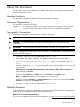
Figure 2 Abnormal Tilt Indicator NOTE: If the tilt indicator shows that an abnormal shipping condition has occurred, write “possible hidden damage” on the bill of lading and keep the packaging. Inspection Precautions • When the shipment arrives, check each container against the carrier's bill of lading. Inspect the exterior of each container immediately for mishandling or damage during transit. If any of the containers are damaged, request the carrier's agent be present when the container is opened.
Tools Required The following tools are required to unpack and install the system: • Standard hand tools, such as a adjustable-end wrench • ESD grounding strap • Digital voltmeter capable of reading ac and dc voltages • 1/2-inch socket wrench • 9/16-inch wrench • #2 Phillips screwdriver • Flathead screwdriver • Wire cutters or utility knife • Safety goggles or glasses • T-10, T-15, T-20, T-25, and T-30 Torx drivers • 9-pin to 25-pin serial cable (HP part number 24542G) • 9-pin to 9-pin
1. Position the packaged cabinet so that a clear area about three times the length of the package (about 12 feet or 3.66 m) is available in front of the unit, and at least 2 feet (0.61 m) are available on the sides. Figure 3 Front of Cabinet Container WARNING! Do not stand directly in front of the strapping while cutting it. Hold the band above the intended cut and wear protective glasses. These bands are under tension. When cut, they spring back and can cause serious eye injury. 2.
3. 4. Lift the cardboard corrugated top cap off the shipping box. Remove the corrugated sleeves surrounding the cabinet. CAUTION: Cut the plastic wrapping material off rather than pulling it off. Pulling the plastic covering off creates an ESD hazard to the hardware. 5. 6. Remove the stretch wrap, the front and rear top foam inserts, and the four corner inserts from the cabinet. Remove the ramps from the pallet and set them aside (Figure 5 (page 12)).
7. Remove the plastic antistatic bag by lifting it straight up off the cabinet. If the cabinet or any components are damaged, follow the claims procedure. Some damage can be repaired by replacing the damaged part. If you find extensive damage, you might need to repack and return the entire cabinet to HP. Inspecting the Cabinet To inspect the cabinet exterior for signs of shipping damage, follow these steps: 1. Look at the top and sides for dents, warping, or scratches. 2.
Installing the System
Moving the Cabinet Off the Pallet 1. Remove the shipping strap that holds the BPSs in place during shipping (Figure 8 (page 15)). Failure to remove the shipping strap will obstruct air flow into the BPS and FEPS. Figure 8 Shipping Strap Location 2. Remove the pallet mounting brackets and pads on the side of the pallet where the ramp slots are located (Figure 9).
Figure 9 Removing the Mounting Brackets WARNING! Do not remove the bolts on the mounting brackets that attach to the pallet. These bolts prevent the cabinet from rolling off the back of the pallet. 3. 4. On the other side of the pallet, remove only the bolt on each mounting bracket that is attached to the cabinet. Insert the ramps into the slots on the pallet. CAUTION: Make sure the ramps are parallel and aligned (Figure 10). The casters on the cabinet must roll unobstructed onto the ramp.
Figure 10 Positioning the Ramps WARNING! Do not attempt to roll a cabinet without help. The cabinet can weigh as much as 1400 pounds (635 kg). Three people are required to roll the cabinet off the pallet. Position one person at the rear of the cabinet and one person on each side. WARNING! Do not attempt to move the cabinet, either packed or unpacked, up or down an incline of more than 15 degrees. 5. Carefully roll the cabinet down the ramp (Figure 11). Figure 11 Rolling the Cabinet Down the Ramp 6.
Unpacking the PDCA At least one PDCA ships with the system. In some cases, the customer might order two PDCAs, the second to be used as a backup power source. Unpack the PDCA and ensure it has the power cord option for installation. Several power cord options are available for the PDCAs. Only options 6 and 7 are currently available in new system configurations (Table 1 (page 18)). Table 2 (page 18) details options 6 and 7.
4. 5. 6. 7. 8. Reattach the ramps to the pallet. Replace the plastic antistatic bag and foam inserts. Replace the cardboard surrounding the cabinet. Replace the cardboard caps. Secure the assembly to the pallet with straps. The cabinet is now ready for shipment. Setting Up the System After a site is prepared, the system is unpacked, and all components are inspected, the system can be prepared for booting.
2. Remove the cardboard from the blower housing (Figure 13). This cardboard protects the housing baffle during shipping. If it is not removed, the fans can not work properly. Figure 13 Removing Protective Cardboard from the Housing NOTE: 3. Double-check that the protective cardboard has been removed.
4. Using the handles on the housing labeled Blower 0 Blower 1, align the edge of the housing over the edge at the top front of the cabinet, and slide it into place until the connectors at the back of each housing are fully mated (Figure 15). Then tighten the thumbscrews at the front of the housing. Figure 15 Installing the Front Blower Housing 5. 6. Unpack each of the four blowers. Insert each of the four blowers into place in the blower housings with the thumbscrews at the bottom (Figure 16).
Figure 16 Installing the Blowers 7. 8. Tighten the thumbscrews at the front of each blower. If required, install housings on any other cabinets that were shipped with the system. Attaching the Side Skins and Blower Side Bezels Two cosmetic side panels affix to the left and right sides of the system. In addition, each system has bezels that cover the sides of the blowers.
Figure 17 Attaching the Rear Side Skin 3. Attach the skin without the lap joint (Front) over the top bracket and under the bottom bracket and gently slide the skin into position.
Figure 18 Attaching the Front Side Skins 4. Push the side skins together, making sure the skins overlap at the lap joint. Attaching the Blower Side Bezels The bezels are held on at the top by the bezel lip, which fits over the top of the blower housing frame, and are secured at the bottom by tabs that fit into slots on the cabinet side panels (Figure 19). Use the same procedure to attach the right and left blower side bezels.
1. Place the side bezel slightly above the blower housing frame. Figure 19 Attaching the Side Bezels 2. 3. Align the lower bezel tabs to the slots in the side panels. Lower the bezel so the bezel top lip fits securely on the blower housing frame and the two lower tabs are fully inserted into the side panel slots. IMPORTANT: Use four screws to attach the side skins to the top and bottom brackets, except for the top bracket on the right side (facing the front of the cabinet).
Attaching the Leveling Feet and Leveling the Cabinet After positioning the cabinet in its final location, to attach and adjust the leveling feet, follow these steps: 1. Remove the leveling feet from their packages. 2. Attach the leveling feet to the cabinet using four T-25 screws. Figure 20 Attaching the Leveling Feet 3. Screw down each leveling foot clockwise until it is in firm contact with the floor. Adjust each foot until the cabinet is level.
Figure 21 Installing the Lower Front Door Assembly 4. 5. Using a T-10 driver, secure the lower door bezel to the front door chassis with 10 of the screws provided. Insert all screws loosely, then tighten them after the bezel is aligned. While another person holds the upper door bezel near the door chassis, attach the ribbon cable to the back of the control panel on the bezel and tighten the two flathead screws (Figure 22).
Figure 22 Installing the Upper Front Door Assembly 6. 7. 8. 9. Feed the grounding strap through the door and attach it to the cabinet. Insert the shoulder studs on the upper door bezel into the holes on the front door metal chassis. Using a T-10 driver, secure the upper door bezel to the metal door with eight of the screws provided. Be sure to press down on the hinge side of the bezel while tightening the screws to prevent misalignment of the bezel. Reattach all filters removed in step 1.
Figure 23 Installing the Rear Blower Bezel 3. 4. Align the bezel over the nuts that are attached to the bracket at the rear of the cabinet. Using a T-20 driver, tighten the two captive screws on the lower flange of the bezel. NOTE: 5. Tighten the screws securely to prevent them from interfering with the door. Close the cabinet rear door. Installing the Front Blower Bezel The front blower bezel is a cosmetic cover for the blowers and is located above the front door.
Figure 24 Installing the Front Blower Bezel 3. 4. Align the bezel over the nuts that are attached to the bracket at the front of the cabinet. Using a T-20 driver, tighten the two captive screws on the lower flange of the bezel. NOTE: 5. Tighten the screws securely to prevent them from interfering with the door. Close the front door. Wiring Check WARNING! LETHAL VOLTAGE HAZARD—Hazardous voltages can be present in the cabinet if incorrectly wired into the site AC power supply.
1. 2. 3. 4. Ensure that the site AC power supply circuit breakers serving the cabinet are set to OFF. Ensure that the cabinet main circuit breaker is set to OFF. Touch one test probe to the site AC power supply ground source. Touch the other test probe to an unpainted metal surface of the cabinet. NOTE: If the digital multimeter (DMM) leads can not reach from the junction box to the cabinet, use a piece of wire connected to the ground terminal of the junction box. 5.
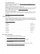
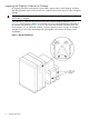
Figure 25 PDCA Assembly for Options 6 and 7 Figure 26 A 4-Wire Connector 32 Installing the System
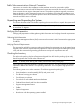
Figure 27 A 5-Wire Connector To install the PDCA, follow these steps: WARNING! 1. 2. 3. Make sure the circuit breaker on the PDCA is OFF. Remove the rear PDCA bezel by removing the four retaining screws. Run the power cord down through the appropriate opening in the floor tile. Insert the PDCA into its slot (Figure 28 (page 33)). Figure 28 Installing the PDCA 4. 5. Using a T-20 driver, attach the four screws that hold the PDCA in place. If required, repeat step 2 through step 4 for the second PDCA.
6. Reinstall the rear PDCA bezel. CAUTION: Do not measure voltages with the PDCA breaker set to ON. Make sure the electrical panel breaker is ON and the PDCA breaker is OFF. 7. 8. Plug in the PDCA connector. Check the voltage at the PDCA: a. Using a T-20 driver, remove the screw on the hinged panel at the top of the PDCA. (Figure 29). b.
Checking Voltage The voltage check ensures that all phases (and neutral, for international systems) are wired correctly for the cabinet and that the AC input voltage is within specified limits. NOTE: If you use a UPS, see applicable UPS documentation for information to connect the server and to check the UPS output voltage. UPS User Manual documentation is shipped with the UPS and is available at www.hp.com/go/bizsupport. 1. 2. 3. 4. Verify that site power is OFF. Open the site circuit breakers.
11. Check that the indicator LED on each power supply is lit. See Figure 31. Figure 31 Power Supply Indicator LED Removing the EMI Panels Remove the front and back electromagnetic interference (EMI) panels to access ports and to visually check whether components are in place and the LEDs are properly illuminated when power is applied to the system.
1. Using a T-20 driver, loosen the captive screw at the top center of the front EMI panel (Figure 32). Figure 32 Removing Front EMI Panel Screw 2. Use the handle provided to remove the EMI panel and set it aside. When in position, the EMI panels (front and back) are tightly in place. Removing them takes controlled but firm exertion. 3. Loosen the captive screw at the lower center of the back EMI panel (Figure 33 (page 37)). Figure 33 Removing the Back EMI Panel 4.
Connecting the Cables The I/O cables are attached and tied inside the cabinet. When the system is installed, these cables must be untied, routed, and connected to the cabinets where the other end of the cables terminate. Use the following guidelines and Figure 34 to route and connect cables. For more information on cable routing, see “Routing the I/O Cables” (page 38). • Each cabinet is identified with a unique color. The cabinet color label is located at the top of the cabinet.
Figure 35 Routing I/O Cables To route cables through the cable groomer at the bottom rear of the cabinet, follow these steps: 1. Remove the cable access plate at the bottom of the groomer. 2. Beginning at the front of the cabinet, route the cables using the following pattern: a. Route the first cable on the left side of the leftmost card cage first. Route it under the PCI-X card cage toward the back of the cabinet and down through the first slot at the right of the cable groomer. b.
Adding an IOX Cabinet There are two (2) IOX cabinet designs available: AF034A and AF092A. Each are different in design. They support the IOX mounted inside to connect the e-link cables to the Superdome server. Ensure your customer's cabinet is identified correctly. In Figure 36 (page 40), note that the AF034A cabinet on the left has 200mm length extension added to the rear with custom vertical side access panels.
2. Install the Support Shelf Rack at the U15 position in the 10KG2 Rack and place the SMS PC onto the shelf. See the following: Connecting the SMS to the Superdome The Superdome Cookbook document is found through the following website (requires authentication): http://athp.hp.com/portal/site/sig/menuitem.260d6c199fc475a058b9d8a989806e01/ In the Search the Sales Library: field, enter the keywords: SMS Cookbook. A second window is displayed with the file information.
SMS Software and Superdome Firmware Downloading Procedure Go to the following URL (requires authentication): http://intranet.hp.com/tsg/WW2/CESL/Pages/SMS-SW-FW.aspx Select the STSD SMS & FW Files link at approximately mid page. The Superdome_Binaries.exe file is a self-extracting archive containing the following Firmware binaries and SMS Software Utilities for Superdome Servers: 1. 2. 3. 4.
6. Enter the following command to un-tar the tar files: tar -xvf h_ipf_(pa or iA)_sxX000_X.Xx.tar HP-UX SMS 1. Create a /opt/firmware/sxX000/X.Xx directory. Example 2 Directory Example sx2000/8.7f 2. Copy the h_ipf_(pa or iA)_sxX000_X.Xx.tar.gz file to the /opt/firmware/sxX000/X.Xx directory. 3. Change the directory to: /opt/firmware/sxX000/X.Xx 4. Enter the following command to un-compress the gzip file: gunzip h_ipf_(pa or ia)_sxX000_X.Xx.tar.gz 5.
IMPORTANT: • The serial number of the desktop PC must be provided. Place an order for the following product: HP Compaq 6200 Pro Series™ QT042AW #ABA 3. When the HP Recovery Manager begins, follow the step-by-step instructions. Configuring the Event Information Tools There are three tools included in the Event Information Tools (EIT) bundle for the SMS. They are the Console Logger, the IPMI Log Acquirer and the IPMI Event Viewer.
IMPORTANT: 4. The 48 V switch on the front panel must be OFF. Turn on the ac breakers on the PDCAs at the back of the each cabinet. • In a large complex, power on the cabinets in one of the two following orders: ◦ 9, 8, 1, 0 ◦ 8, 9, 0, 1 • On the front and back panels, the HKP and the Present LEDs illuminate (Figure 37). • On cabinet 0, the HKP and the Present LEDs illuminate, but only the HKP LED illuminates on cabinet 1 (the right cabinet).
5. Examine the BPS LEDs (Figure 38). When on, the breakers on the PDCA distribute ac power to the BPSs. Power is present at the BPSs when: • The amber LED next to the AC0 Present label is on (if the breakers on the PDCA are on the left side at the back of the cabinet). • The amber LED next to the AC1 Present label is on (if the breakers on the PDCA are on the right side at the back of the cabinet).
1. Connect one end of the RJ-45 LAN cable to the LAN port on the MP (Figure 39). Figure 39 MP LAN Connection Location 2. Connect the other end of the LAN cable to the customer-designated LAN port. Obtain the IP address for the MP from the customer. Connect the dial-up modem cable between the MP modem and the customers phone line connection. Setting the Customer IP Address NOTE: The default IP address for the customer LAN port on the MP is 192.168.1.1.
1. From the MP Command Menu prompt MP:CM>, enter lc (LAN configuration). The screen displays the default values and asks if you want to modify them. TIP: Write down the information, as it may be required for future troubleshooting. If you are not already in the Command Menu, enter ma to return to the Main Menu, then enter cm. The LAN configuration screen appears (Figure 40). Figure 40 LAN Configuration Screen 2.
Figure 41 The ls Command Screen To return to the MP Main Menu, enter ma. To exit the MP, enter x at the MP Main Menu. 10. Check the settings for the model string, UUID, and Creator Product Name using the ID command. For example: MP modifiable stable complex configuration data fields.
1. On the SMS, open the following command prompt windows: • One console window for each partition (MP CO option) • One for initializing the RS command from the MP • One for monitoring partition status (MP VFP option) In each window, connect to the MP by entering the following: telnet Or telnet 2. Enter the appropriate login and password at the MP prompts (Figure 42). Figure 42 Logging In The MP Main Menu appears (Figure 43). Figure 43 Main MP Menu 3. 4.
Figure 44 MP Command Option 5. In the another window, open the Virtual Front Panel (VFP) by entering vfp at the MP prompt (Figure 45). Use this window to observe partition status. Figure 45 MP Virtual Front Panel 6. From the VFP menu, enter s to select the whole system, or enter the partition number to select a particular partition. An output similar to Figure 46 appears. In this example, no status is listed because the system 48 V has not been switched on.
7. For each of the remaining windows, open the partition console for each partition by enter co at the MP> prompt (Figure 47). These windows open blank. NOTE: If information appears in the windows, it means nothing because the cabinet is powered off. Figure 47 MP Console Option Powering On the System 48 V Power Supply To power on the system 48 V power supply, follow these steps: 1. Switch on the 48 V supply from each cabinet front panel.
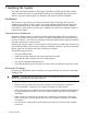
Figure 48 HP Integrity Superdome/sx2000 EFI Boot Manager Use the up and down arrow keys on the keyboard to highlight EFI Shell (Built-in) and press Enter. Do this for all partitions. After you start the EFI Shell, the console window displays the EFI shell prompt (Figure 49). Figure 49 EFI Shell Prompt NOTE: If autoboot is enabled for an nPartition, you must interrupt it to stop the boot process at the EFI firmware console. The VFP indicates that each partition is at system firmware console (Figure 50).
Figure 50 HP Integrity Superdome/sx2000 Partitions at System Firmware Console Booting an HP 9000 sx2000 Server to BCH After you power on the server or use the MP BO command to boot an nPartition past boot-is-blocked (BIB), the nPartition console shows activity while the firmware initializes and stops at the BCH Main Menu (the Main Menu: Enter command or menu> prompt). To redisplay the current menu and its available commands, enter the BCH DI command.
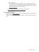
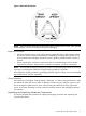
1. To observe the power status, enter ps at the CM> prompt. A status screen similar to the one in Figure 51 appears. Figure 51 Power Status First Window 2. At the Select Device: prompt, enter b then the cabinet number to check the power status of the cabinet. Observe Power Switch: on and Power: enabled (Figure 52). Figure 52 Power Status Window Figure 52 shows that cells are installed in slots 0 and 4. In the cabinet, verify that cells are physically located in slots 0 and 4. 3.
Figure 53 Power Status Showing State of UGUY LEDs 4. Verify that there is an asterisk (*) in the columns marked MP, CLU, and PM. IMPORTANT: An asterisk (*) appears in the MP column only for cabinet 0; that is, the cabinet containing the MP. Verify that there is an asterisk (*) for each of the cells installed in the cabinet by comparing what is in the Cells column with the cells located inside the cabinet.
IMPORTANT: power. After scan testing successfully completes, reset the complex by cycling the AC Power Cycling After Using JET After using JET, you must recycle the system power because the offline diagnostic can deallocate the CPUs. To remove the 48 V power, run the MP pe command. Then cycle the ac breakers on the rear of the cabinets. Leave power off for about 30 seconds to allow the backplane CSRs to reset.
Figure 54 Attaching Rear Kick Plates 4. 5. 6. Perform steps 1–3 on the right kick plate. Position the upper flange of the center kick plate under the I/O trays complementary mounting bracket, to retain the center kick plate top flanges. No top screws are needed on the center kick plate. Orient this asymmetrical bracket with the hole located nearest the edge in the up position. Using a T-20 driver, tighten the thumbscrews at the bottom of the center kick plate.
Figure 55 Cell Board Ejectors 4. Reinstall the front EMI panel (Figure 56). Figure 56 Front EMI Panel Flange and Cabinet Holes a. b. Hook the flange at the lower corners of the EMI panel into the holes on the cabinet. Position the panel at the top lip, and lift the panel up while pushing the bottom into position. If needed, compress the EMI gasket to seat the panel properly. c. 5. Reattach the screw at the top of the EMI panel. Check that the cables inside the rear enclosure are secure.
6. Reinstall the back EMI panel (Figure 57 (page 60)). a. Align the lip inside the cabinet with the lip on the EMI panel. Figure 57 Reinstalling the Back EMI Panel b. c. Push the EMI panel up and in. If needed, compress the EMI gasket at the top of the enclosure to get the panel to seat properly. Reattach the screw at the bottom of the EMI panel. Conducting a Post-Installation Check After the system is installed in a computer room and verified, conduct the post-installation check.
Index A E ac power verification 4-wire PDCA, 31 5-wire PDCA, 31 AC0 Present LED, 46 AC1 Present LED, 46 ejectors cell board, 58 electrostatic discharge, 6 EMI panel installing, 59 removing, 36 equipment returning, 18 B bezel attaching front bezel, 29 attaching rear bezel, 28 attaching side bezels, 22 blower bezels (See also "bezel"), 22 blower housings installing, 19 unpacking, 19 booting checking cabinet power status, 55 checking installed cell slot locations, 55 invoking the EFI shell, 53 output from
port 0, 48 port 1, 48 status, 48 LED AC0 Present, 46 AC1 Present, 46 HKP (housekeeping), 45 Present, 45 leveling feet attaching, 26 M U unpacking blower housings, 19 blowers, 19 pallet ramps, 12 PDCA, 18 system cabinet, 10 W wrist strap usage, 6 MAC address, 48 moving the system, 19 MP displaying the customer LAN parameters, 48 exiting the main menu, 49 invoking a partition console, 52 invoking the virtual front panel, 51 physical connection to the customer LAN, 46 returning to the main menu, 49 setting