Site Preparation Guide hp Integrity Superdome and hp 9000 Superdome Fifth Edition Manufacturing Part Number: A5201-96046 February 2005 USA
Legal Notices Copyright 2005 Hewlett-Packard Development Company, L.P. The information contained herein is subject to change without notice. The only warranties for HP products and services are set forth in the express warranty statements accompanying such products and services. Nothing herein should be construed as constituting an additional warranty. HP shall not be liable for technical or editorial errors or omissions contained herein.
Contents 1. Introduction Basic System Building Blocks . . . . . . . . . . . . . . . . . . . . . . . . . . . . . . . . . . . . . . . . . . . . . . . . . . . . . . . . . . . 3 2. Dimensions and Weights Component Dimensions . . . . . . . . . . . . . . . . . . . . . . . . . . . . . . . . . . . . . . . . . . . . . . . . . . . . . . . . . . . . . . . 10 Component Weights . . . . . . . . . . . . . . . . . . . . . . . . . . . . . . . . . . . . . . . . . . . . . . . . . . . . . . . . . . . . . . . . . .
Contents Cell Population . . . . . . . . . . . . . . . . . . . . . . . . . . . . . . . . . . . . . . . . . . . . . . . . . . . . . . . . . . . Partition Size . . . . . . . . . . . . . . . . . . . . . . . . . . . . . . . . . . . . . . . . . . . . . . . . . . . . . . . . . . . . I/O Chassis Allocation . . . . . . . . . . . . . . . . . . . . . . . . . . . . . . . . . . . . . . . . . . . . . . . . . . . . . System Planner . . . . . . . . . . . . . . . . . . . . . . . . . . . . . . . . . . . . . . . . . . . . .
Preface v
Scope This document is intended for viewing by hp service personel and its customers. This document does not describe system software or partition configuration operations in any detail. For detailed information concerning those topics refer to the hp System Partitions Guide (5990-8170A).
Book Layout This document contains the following chapters and appendices: • Chapter 1, Introduction—Brief introduction to the hp Integrity Superdome • Chapter 2, Dimensions and Weights—Necessary physical specifications of the servers • Chapter 3, Electrical Specifications—Necessary electrical specifications of the servers • Chapter 4, Environmental Requirements—Special requirements of the server • Chapter 5, Facility Guidelines—Preparation of the customer’s site before installation of the hp Integr
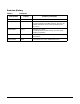
Revision History Table 1 Part Number Revisions Edition Summary of Changes A5201-96018 First Initial Release. September 2003 A5201-96022 Second Released March, 2004. Includes updates for PA-8800, PA-RISC processor for hp9000 Superdome, plus numerous additions and corrections. A5201-96027 Third Released June, 2004. Includes updates for dual-core IPF processor forhp Integrity Superdome. A5201-96032 Fourth Released September, 2004. Added general corrections and updates.
1 Introduction The Superdome family of high-end computers has two new members: hp Integrity Superdome and hp 9000 Superdome. Improvements over the Superdome predecessors include higher processor performance, increased local cell board memory bandwidth, and increased scalability. The hp Integrity Superdome uses the Itanium® 2 single- and dual-core processors, and the hp 9000 Superdome uses the dual-core PA-8800.
Introduction The biggest differences between hp Integrity Superdome servers or hp 9000 Superdome servers and earlier Superdome family products include (but are not limited to): • Cell board design using either of the following processors: 1. Itanium® 2 single- and dual-core for hp Integrity Superdome 2. PA-8800 PA-RISC dual-core for hp 9000 Superdome • Firmware packages. — Management Processor — CLU—clocks, I2C bus, and so on.
Introduction Basic System Building Blocks Basic System Building Blocks The basic system building blocks used to configure a system are as follows: Figure 1-2 on page 5 illustrates a typical SD16 or SD32 installation. Figure 1-3 on page 6 illustrates a typical SD64 installation. Figure 1-4 on page 7 illustrates a typical SD64 and I/O expansion cabinet installation. Server Cabinet The server cabinet is the main building block. An SD64 comprises two server cabinets interconnected.
Introduction Basic System Building Blocks Figure 1-1 Server Cabinet Components Fans Cell Boards I/O Chassis I/O Fans BPS PDCA 4 Chapter 1
Introduction Basic System Building Blocks Figure 1-2 Typical SD16/SD32 Installation 60SP001A 4/17/00 Chapter 1 5
Introduction Basic System Building Blocks Figure 1-3 Typical SD64 Installation 60SP002A 4/17/00 6 Chapter 1
Introduction Basic System Building Blocks Figure 1-4 Typical Installation with IOX 60SP003A 4/26/00 Support Management Station The hp Integrity Superdome and hp 9000 Superdome SMS is an hp Proliant M350-G3 PC, either a desktop or a rack-mounted unit. The rack-mounted unit uses a TFT-5600 rack-mount LCD monitor and keyboard.
Introduction Basic System Building Blocks 8 Chapter 1
2 Dimensions and Weights Chapter 2 9
Dimensions and Weights Component Dimensions Component Dimensions Table 2-1 lists the dimensions for the cabinet and components. Table 2-2 list the dimensions for optional IOX cabinets. Table 2-1 Component Server Component Dimensions Width (in. / cm) Depth (in. / cm) Height (in. / cm) Maximum Quantity per Cabinet Cabinet 30 / 76.2 48 / 121.9 77.2 / 195.6 1 Cell board 16.5 / 41.9 20.0 / 50.2 3.0 / 7.6 8a Cell board power board (OCPB) 16.5 / 41.9 10.125 / 25.7 3.0 / 7.
Dimensions and Weights Component Weights Component Weights Table 2-3 lists the server and component weights. NOTE Refer to the appropriate documents to determine the weight of the SMS and any console that will be used with this server. Table 2-3 System Component Weights Component Weight Per Unit (lb. / kg) Quantity Weight (lb. / kg) Chassisa 745.17 / 338.1 1 745.17 / 338.10 Cell Board w/o Power Board and DIMMs 17.23 / 7.81 8 137.84 / 62.54 Cell Power Board 8.05 / 3.65 8 64.40 / 29.
Dimensions and Weights Shipping Dimensions and Weights Shipping Dimensions and Weights Table 2-5 lists the dimensions and weights of the Support Management Station and a single cabinet with shipping pallet. Table 2-5 Miscellaneous Dimensions and Weights Equipment Width (in. / cm) Depth/Length (in. / cm) Height (in. / cm) Weight (lb. / kg) System on shipping palleta b c 39.00 / 99.06 48.63 / 123.5 73.25 / 186.7) 1360.8lbs / 618.54) Blowers/Frame on shipping pallet 40.00 / 101.6 48.00 / 121.
3 Electrical Specifications The following specifications are based on HP Environmental Class C2. Class C2 is a controlled computer room environment where products are subject only to controlled temperature and humidity extremes. Throughout this chapter each specification is defined as thoroughly as possible to ensure that all data is considered to ensure a successful site preparation and system installation.
Electrical Specifications Grounding Grounding The site building shall provide a safety ground/protective earth for each AC service entrance to all cabinets. This equipment is CLASS 1 and requires full implementation of the grounding scheme to all equipment connections. Failure to attach Protective Earth results in loss of regulatory compliance and creates a possible safety hazard.
Electrical Specifications Circuit Breaker Circuit Breaker Each cabinet using a three-phase, four-wire input requires dedicated circuit breaker to support the Marked Electrical current of 44A per phase. The facility electrician and local service codes will determine proper circuit breaker selection. Each cabinet using a three-phase five-wire input requires a dedicated circuit breaker to support the Marked Electrical current of 24A per phase.
Electrical Specifications Power Options Power Options Table 3-1 describes the available power options. It may be unusual to list Options 6 and 7 and not 1 and 2. The options listed are consistent with previous options for earlier Superdome systems.
Electrical Specifications Power Options Figure 3-1 PDCA Locations PDCA 0 PDCA 1 60SP040A 8/20/01 Power Cords This section discusses the different possibilities for PDCA power cords. Pre-wired PDCAs Options 6 and 7 All servers are delivered with the appropriate cable and plug. The mating in-line connector is not provided. IMPORTANT Verify that the source power is correct for the appropriate PDCA wiring.
Electrical Specifications Power Options • To verify the proper wiring for a 4-wire PDCA, use a DVM to measure the voltage at the in-line connector. Voltage should read 200 - 240 Vac phase-to-phase as measured between the connector pins as follows: L1 to L2, L2 to L3, L1 to L3. • To verify the proper wiring for a 5-wire PDCA, use a DVM to measure the voltage at the connector. Voltage should read 200 - 240 Vac phase-to-neutral as measured between the connector pins as follows: L1 to N, L2 to N, L3 to N.
Electrical Specifications Power Options IMPORTANT Ensure that your DVM is capable of measuring AC voltages of at least 500VAC. A number of 5-wire power distribution systems may have phase-to-phase voltages in excess of 400VAC. Many hand-held volt meters are limited to 300VAC.
Electrical Specifications Power Options To remove the existing cable from the PDCA, begin be removing the five T-10 Torx screws detailed in Figure 3-5 on page 21. Then remove the bottom panel of the PDCA. Retain the panel and screws for future use. NOTE The cable removal and installation requires only the bottom panel to be removed. For image clarity, Figure 3-5 does not show cable or cable strain relief. Step 1. Locate and remove the PDCAs. Step 2. Remove the five screws securing the bottom of the PDCA.
Electrical Specifications Power Options Step 5. Remove the cable from the PDCA. Keep all retaining hardware for use during installation of the new cable. Figure 3-5 PDCA Cable Access (5-Wire Unit Shown) L3-L1 L2-L3 L1-L2 L3 L2 L1 1.36 in DIA 3.
Electrical Specifications Power Options Figure 3-6 PDCA Input Wiring Connections (5-Wire Unit Shown) L3-L1 L2-L3 L1-L2 N 60SP041A 7/13/00 Cable Installation NOTE These procedures may be used for early deliveries consisting of either option 1 or option 2 as well as those later systems delivered with PDCA cables attached. Select the proper cable using the following criteria. • Each cabinet using a 3-phase, 4-wire input is required to have a four-conductor cable.
Electrical Specifications Power Options Step 5. Using the five screws retained from the removal procedure, replace the bottom panel on the PDCA. Refer to Figure 3-5 on page 21 for panel installation details. Step 6. To verify the proper wiring to a 4-wire PDCA, use a DVM to measure the voltage at the test points. Voltage should read 200 - 240 Vac phase-to-phase as measured between the test points as follows: L1 to L2, L2 to L3, L1 to L3.
Electrical Specifications Power Options NOTE Figure 3-8 Figure 3-7 shows a 4-wire cable for illustrative purposes only. 5-wire cable is dimensionally identical regarding insulation and jacket removal. The only exception is the number of conductors.
Electrical Specifications Power Options Customer Installation Options Figure 3-10 and Figure 3-11 detail a suggested configuration for connecting the PDCA when the use of rigid conduit is required or desired. Using a 2- to 4-inch nipple and a 90o elbow allows the conduit to pass through the raised floor at a point immediately past the cabinet. This prevents the conduit from extending beyond the cabinet.
Electrical Specifications System Power Requirements System Power Requirements Table 3-3 and Table 3-4 list the AC power requirements for a hp Integrity Superdome and hp 9000 Superdome systems. These tables provide information to help determine the amount of AC power needed for your computer room.
Electrical Specifications Component Power Requirements Component Power Requirements Table 3-3 and Table 3-4 list the AC power requirements for a hp Integrity Superdome and hp 9000 Superdome systems. These tables provide information to help determine the amount of AC power needed for your computer room.
Electrical Specifications I/O Expansion Cabinet Power Requirements I/O Expansion Cabinet Power Requirements The I/O expansion cabinet requires a single phase 200-240VAC input. Table 3-5 lists the AC power requirements for the I/O expansion cabinet.
Electrical Specifications I/O Expansion Cabinet Power Cords I/O Expansion Cabinet Power Cords Table 3-7 lists the power cords for the I/O expansion cabinet.
Electrical Specifications I/O Expansion Cabinet Power Cords 30 Chapter 3
4 Environmental Requirements Chapter 4 31
Environmental Requirements Temperature and Humidity Specifications Temperature and Humidity Specifications Table 4-1 Controlled Computer Room Environment Specifications Relative Humidity %; Non condensing Temperature (dry bulb οC)a Dew Pointb Allowablec,d Recommendede Allowabled Recommendede 15 to 32 (59ο to 90ο F) 20 to 25 (68ο to 77ο F) 20 to 80 40 to 55 17 Rate of Change (°C/hr., max) 5 a. Dry bulb temperature is the regular ambient temperature.
Environmental Requirements Power Dissipation Power Dissipation Table 4-3 and Table 4-4 show the power requirements by configuration (i.e. number of cell boards, amount of memory per cell, and number of I/O chassis) for the hp Integrity Superdome and the hp 9000 Superdome, respectively. There are two columns of power numbers (Watts). The Power Breaker column shows the power used to size the wall breaker at the installation site. The Typical Power column shows typical power.
Environmental Requirements Power Dissipation Table 4-3 Typical hp Integrity Superdome Configurations Breaker Power (Watts)a 3-Pole Breaker Size (Amperes)a,b 4-Pole Breaker Size (Amperes)a,c,d 33406 12335 40 25 8450 28834 10647 40 25 4 8680 29619 10937 40 25 8 2 8170 27878 10294 35 20 8 4 4 8400 28663 10584 35 20 8 4 2 7700 26275 9702 35 20 6 16 4 7370 25149 9286 35 20 6 16 2 6660 22726 8392 30 20 6 8 4 7010 23920 8833 30 20 6 8 2 6300 21
Environmental Requirements Power Dissipation c. An input power source supplied from a three-pole plus PE, four-wire system may be wired as either: 200VAC phase-to-phase, plus a PE ground. The three phase input voltage to the equipment is connected phase-to-phase. The neutral terminal in the PDCA is not connected. 208VAC phase-to-phase, plus a PE ground. The three phase input voltage to the equipment is connected phase-to-phase. The neutral terminal in the PDCA is not connected.
Environmental Requirements Power Dissipation Table 4-4 Typical hp 9000 Superdome Configurations Breaker Power (Watts)a 3-Pole Breaker Size (Amperes)a,b 4-Pole Breaker Size (Amperes)a,c,d 30840 11388 40 25 7698 26268 9699 40 25 4 7928 27053 9989 40 25 8 2 7418 25312 9347 35 20 8 4 4 7648 26097 9636 35 20 8 4 2 6948 23709 8754 35 20 6 16 4 6806 23224 8576 35 20 6 16 2 6096 20801 7681 30 20 6 8 4 6446 21996 8122 30 20 6 8 2 5736 19573 7227
Environmental Requirements Power Dissipation c. An input power source supplied from a three-pole plus PE, four-wire system may be wired as either: 200VAC phase-to-phase, plus a PE ground. The three phase input voltage to the equipment is connected phase-to-phase. The neutral terminal in the PDCA is not connected. 208VAC phase-to-phase, plus a PE ground. The three phase input voltage to the equipment is connected phase-to-phase. The neutral terminal in the PDCA is not connected.
Environmental Requirements Acoustic Noise Specification Acoustic Noise Specification The acoustic noise specification as follows: • 8.2 bel (sound power level) • 65.1 dBA (sound pressure level at operator position) The above levels are appropriate for dedicated computer room environments, not office environments.
Environmental Requirements Air Flow Air Flow hp Integrity Superdome and hp 9000 Superdome systems require the cabinet air intake temperature to be between 20ο C and 30ο C at 2400 CFM. Any cooling system layouts described in Chapter 2 can be adapted to cool the system. Figure 4-1 on page 39 illustrates the location of the inlet and outlet airducts on a single cabinet.
Environmental Requirements Air Flow 40 Chapter 4
5 Facility Guidelines Chapter 5 41
Facility Guidelines Electrical and Environmental Guidelines Electrical and Environmental Guidelines Electrical Factors Proper design and installation of a power distribution system for a server requires specialized skills. Those responsible for this task must have a thorough knowledge and understanding of appropriate electrical codes and the limitations of the power systems for computer and data processing equipment.
Facility Guidelines Electrical and Environmental Guidelines The minimum recommended illumination level is 70 foot-candles (756 lumens per square meter) when the light level is measured at 30 inches (76.2 cm) above the floor. Power Quality This equipment is designed to operate over a wide range of voltages and frequencies. It has been tested and shown to comply with EMC Specification EN50082. However, damage can occur if these ranges are exceeded.
Facility Guidelines Electrical and Environmental Guidelines Wire Selection Use copper conductors instead of aluminum, as aluminum’s coefficient of expansion differs significantly from that of other metals used in power hardware. Because of this difference, aluminum conductors can cause connector hardware to work loose, overheat, and fail. Raceway Systems (Electrical Conduits) Raceways (electrical conduits) form part of the protective ground path for personnel and equipment.
Facility Guidelines Electrical and Environmental Guidelines NOTE The green wire ground conductor mentioned above may be a black wire marked with green tape. Computer Safety Ground Ground all computer equipment with the green (green/yellow) wire included in the branch circuitry. The green (green/yellow) wire ground conductors should be connected to the appropriate power panel and should be sized per applicable codes (based on circuit over current device ratings).
Facility Guidelines Electrical and Environmental Guidelines Best Practices • Use a 2ft by 2ft grid. • Flat braid is preferred over round wire. • Exothermic welds are preferred over mechanical connections. • All transformers mounted on the floor should have an X0 bond to floor. • All air conditioning cabinets mounted on the floor with a bonding connection to the floor. • A vertical building steel grounding point is preferred over long wire runs to electrical service entrance.
Facility Guidelines Electrical and Environmental Guidelines Wiring Connections Expansion and contraction rates vary among different metals. Therefore, the integrity of an electrical connection depends on the restraining force applied. Connections that are too tight compress or deform the hardware and causes it to weaken. This usually leads to high impedance causing circuit breakers to trip.
Facility Guidelines Electrical and Environmental Guidelines • Ensure a minimum ceiling height of 12 inches between the top of the server and the ceiling. Ensure all ceiling clips are in place. Cooling Requirements Air conditioning equipment requirements and recommendations are described in the following sections.
Facility Guidelines Electrical and Environmental Guidelines Table 5-1 Controlled Computer Room Environment Specifications Temperature (dry bulb οC)a Relative Humidity %; Noncondensing Allowablec,d Recommendede Allowabled Recommendede 15 - 32 (59ο to 90ο F) 20 - 25 (68ο to 77ο F) 20 - 80 40 - 55 Rate of Chg (°C/hr, max) Dew Pointb 17 5 a. Dry bulb temperature is the regular ambient temperature. Derate maximum dry bulb temperature 1°C/300 m above 900 m. b. Must be noncondensing environment.
Facility Guidelines Electrical and Environmental Guidelines An air distribution system should be zoned to deliver an adequate amount of supply air to the cooling air intake vents of the computer system equipment cabinets. Supply air temperature should be maintained within the following parameters: • Ceiling supply system—From 55° F (12.8° C) to 60° F (15.6° C) • Floor supply system—At least 60° F (15.
Facility Guidelines Electrical and Environmental Guidelines Figure 5-5 on page 54 illustrates a typical computer room above ceiling ducted air distribution system (DRA).
Facility Guidelines Electrical and Environmental Guidelines Figure 5-3 Underfloor Air Distribution System Roof or floor slab above Ceiling cavity Ducted return air (DRA) Ceiling Down-flow A/C equipment Cooled supply air Floor cavity supply plenum Computer air intake Perforated floor panel (typical) Raised floor Floor slab 52 Chapter 5
Facility Guidelines Electrical and Environmental Guidelines Figure 5-4 Ceiling Plenum Air Distribution System To and From Air Handling Unit (if used) Supply Air Ductwork Roof or floor slab above Ceiling Plenum Return Air (CPRA) Return Air Grill Ceiling Diffuser Up-Flow AC Equipment Ceiling Typical Computer Air Discharge Computer Air Intake Cooled Air Supply Chapter 5 53
Facility Guidelines Electrical and Environmental Guidelines Figure 5-5 Above Ceiling Ducted Air To and From Air Handling Unit (if used) Supply Air Ductwork Roof Or Floor Slab Above Ducted Return Air (DRA) Return Air Grill Ceiling Diffuser Up-Flow AC Equipment Ceiling Typical Computer Air Discharge Slab Floor Computer Air Intake Cooled Air Supply Humidity Level Maintain proper humidity levels. High humidity causes galvanic actions to occur between some dissimilar metals.
Facility Guidelines Electrical and Environmental Guidelines CAUTION Low humidity contributes to undesirably high levels of electrostatic charges. This increases the electrostatic discharge (ESD) voltage potential. ESD can cause component damage during servicing operations. Paper feed problems on high-speed printers are usually encountered in low-humidity environments. Low humidity levels are often the result of the facility heating system and occur during the cold season.
Facility Guidelines Electrical and Environmental Guidelines Metallic Particulate Contamination Metallic particulates can be especially harmful around electronic equipment. This type of contamination may enter the data center environment from a variety of sources, including but not limited to raised floor tiles, worn air conditioning parts, heating ducts, rotor brushes in vacuum cleaners or printer component wear.
Facility Guidelines Electrical and Environmental Guidelines • Use conductive tables and chairs. • Use a grounded wrist strap (or other grounding method) when handling circuit boards. • Store spare electronic modules in antistatic containers. • Maintain recommended humidity level and airflow rates in the computer room. Acoustics Computer equipment and air conditioning blowers cause computer rooms to be noisy.
Facility Guidelines Site Guidelines Site Guidelines This section describes facility characteristics and provides guidelines for preparing the computer room. • “Facility Characteristics” on page 58 discusses architectural issues. • “Space Requirements” on page 61 discusses the amount of floor space required by the components. NOTE Refer to Appendix C for templates to aid in locating caster contact area and caster/leveling foot centers.
Facility Guidelines Site Guidelines Floor-Loading Terms Table 5-3 defines floor-loading terms. Table 5-3 Term Floor-Loading Terms Definition Dead load Weight of the raised-panel floor system, including the understructure. Expressed in lb/ft2 (kg/m2). Live load Load the floor system can safely support. Expressed in lb/ft2 (kg/m2). Concentrated load Load a floor panel can support on a 1-in2 (6.
Facility Guidelines Site Guidelines In the event that the flooring is being replaced or a new floor is being installed, Tate Access Floors recommends its Series 1250 all-steel access floor with bolt-together stringers and 24 in. (61.0 cm) by 24 in. (61.0 cm) floor panels be used to support the Superdome installation.
Facility Guidelines Site Guidelines Space Requirements This section contains information about space requirements for a Superdome server. This data should be used as the basic guideline for space plan developments. Other factors, such as airflow, lighting, and equipment space requirements, must also be considered. Delivery Space Requirements There should be enough clearance to move equipment safely from the receiving area to the computer room.
Facility Guidelines Site Guidelines Equipment Footprint Templates Equipment footprint templates are provided in Appendix C to show basic equipment dimensions and space requirements for servicing. Be sure to use the appropriate templates for the equipment that is to be installed. The service areas shown on the template drawings are lightly shaded. Removable copies of the equipment footprint templates are located in Appendix C.
6 Pre-Installation Survey This chapter provides a pre-installation survey information packet consisting of an information form and checklists to be used to evaluate a computer facility. The checklists information sheets and information forms should be filled out by the customer and a Hewlett-Packard representative.
Pre-Installation Survey Pre-Installation Survey Content Pre-Installation Survey Content The site pre-installation survey information is designed to identify problems that might occur before, during, or after the installation of the system. It contains the following items: • Pre-installation checklists—Verify the customer site is ready for the equipment installation. • Pre-installation survey information sheets—List customer name, address, and corresponding Hewlett-Packard sales personnel.
Pre-Installation Survey Typical Installation Schedule Typical Installation Schedule The following schedule lists the sequence of events for a typical system installation: • 60 days before installation — Floor plan design completed and mailed to Hewlett-Packard • 30 days before installation — Primary power and air conditioning installation completed — Telephone and data cables installed — Fire protection equipment installed — Major facility changes completed — Special delivery requirements defined — Site
Pre-Installation Survey Site Inspection Site Inspection Table 6-1 contains a sample of the Customer and Hewlett-Packard information required. Table 6-2 contains a sample site inspection checklist. IMPORTANT Ensure that the customer is aware of the iCOD email requirements. That is, each bootable partition requires a connection to the internet to send email to notify Hewlett-Packard that the customer has allocated additional CPUs beyond the amount initially purchased.
Pre-Installation Survey Site Inspection To ensure compliance with item 10 of Table 6-2, provide a copy of Appendix D to the customer to use a worksheet to identify required names and addresses for the LAN. NOTE Table 6-2 Site Inspection Checklist Please check either Yes or No. If No, include comment or date Comment or Date Computer room No. Area or condition 1. Is there a completed floor plan? 2. Is there adequate space for maintenance needs? Front 42 in (106 cm) min.
Pre-Installation Survey Site Inspection Table 6-2 Site Inspection Checklist (Continued) Please check either Yes or No. If No, include comment or date 11. Are floor tiles in good condition and properly braced? 12. Metallic particulate test required. Comment or Date Power and lighting No. Area or condition 13. Are lighting levels adequate for maintenance? 14. Are there ac outlets available for servicing needs? (i.e. vacuuming) 15.
Pre-Installation Survey Site Inspection Table 6-2 Site Inspection Checklist (Continued) Please check either Yes or No. If No, include comment or date 26. Comment or Date Are there any equipment servicing hazards (loose ground wires, poor lighting, etc.)? Cooling No. Area or condition 27. Can cooling be maintained between 68° and 77° (20° and 25° C)? 28. Can temperature changes be held to 9° (5 ° C) per hour? 29. Can humidity level be maintained between 40% and 55%? 30.
Pre-Installation Survey Delivery Survey Delivery Survey The delivery survey form shown in Figure 6-1 on page 71 and Figure 6-2 on page 72 lists delivery or installation requirements. If any of the items on the list apply, enter the appropriate information in the areas provided on the form. Special instructions or recommendations should be entered on the Special Instructions or Recommendations form.
Pre-Installation Survey Delivery Survey • Special security requirements applicable to the facility, such as security clearance Figure 6-1 Delivery Survey (Part 1) DELIVERY CHECKLIST DOCK DELIVERY Yes Is dock large enough for a semitrailer? No Circle the location of the dock and give street name if different than address. North East West South STREET DELIVERY Circle the location of access door and list street name if different than address.
Pre-Installation Survey Delivery Survey Figure 6-2 Delivery Survey (Part 2) ELEVATOR Fill in the following information if an elevator is required to move equipment. Capacity (lb or kg) Depth Height Width Height Depth Width STAIRS Please list number of flights and stairway dimensions.
Pre-Installation Survey Delivery Survey Chapter 6 73
Pre-Installation Survey Delivery Survey 74 Chapter 6
A Templates This appendix contains blank floor plan grids and equipment templates. Combine the necessary number of floor plan grid sheets to create a scaled version of the computer room floor plan. Figure A-1 illustrates the locations required for the cable cutouts.
Templates Figure A-2 on page 78 illustrates the overall dimensions required for an hp Integrity Superdome SD32 or an hp 9000 Superdome SD32 system.
Templates Figure A-3 on page 79 illustrates the overall dimensions required for a SD64 system. Figure A-1 Cable Cutouts and Caster Locations 14 in 35.6 cm 5.1 in 13.0 cm (edge of cutout) 3.8 in 9.5 cm (center of foot) 7 in 1 in 17.8 cm Service 7 in Area 17.8 cm 2.5 cm Server 4X Leveling feet 1.25" dia 3.2 cm Rear Door 36 in 91.4 cm 48 in 122 cm 126 in 320 cm IO Cable Exit 4X Caster 7 in 17.8 cm 7.8 in 19.9 cm Service Area 5.1 in 12.8 cm 30 in 76.2 cm 42 in 106.
Templates Figure A-2 SD16 /SD32 Space Requirements NOTE: 12" Minimum Clearance Required Between Top Of Cabinet and Ceiling 4 ft 1220 mm 126 in 320 cm Server Service Area 30 in 762 mm 36 in 91.4 cm Service Area 6.4 ft 1.95 m 48 in 122.0 cm 42 in 106.7 cm NOTE: 48 in Is Recommended 42 in Is Minimum Allowable 30 in 76.
Templates Figure A-3 SD64 Space Requirements NOTE: 12" Minimum Clearance Required Between Top Of Cabinet and Ceiling 77 in 196 cm 48 in 122 cm 60 in 152.4 cm 36 in 91.4 cm Service Area Server Server 126 in 320 cm Service Area 48 in 122.0 cm 42 in 106.7 cm NOTE: 48 in Is Recommended 42 in Is Minimum Allowable 60 in 152.
Templates Equipment Footprint Templates Equipment Footprint Templates Equipment footprint templates are drawn to the same scale as the floor plan grid (1/4 inch = 1 foot). These templates are provided to show basic equipment dimensions and space requirements for servicing. The service areas shown on the template drawings are lightly shaded. The equipment templates should be used with the floor plan grid to define the location of the equipment that will be installed in your computer room.
Templates Computer Room Layout Plan Computer Room Layout Plan Use the following procedure to create a computer room layout plan: Step 1. Remove several copies of the floor plan grid. Step 2. Cut and join them together (as necessary) to create a scale model floor plan of your computer room. Step 3. Remove a copy of each applicable equipment footprint template. Step 4. Cut out each template selected in Step 3; then place it on the floor plan grid created in Step 2. Step 5.
Templates Computer Room Layout Plan SD32, SD64, and I/O Expansion Cabinet Templates Scale: 1/4 inch = 1 foot Service Area Server Service Area Server Server Service Area Service Area Service Area Service Area Server Service Area Server Server Service Area IOX Cabinet Service Area Service Area IOX Cabinet Service Area Service Area 60SP017A 7/16/00 82 Appendix A
Templates Computer Room Layout Plan SD32, SD64, and I/O Expansion Cabinet Templates Scale: 1/4 inch = 1 foot Service Area Server Service Area Server Server Service Area Service Area Service Area Service Area Server Service Area Server Server Service Area IOX Cabinet Service Area Service Area IOX Cabinet Service Area Service Area 60SP017A 7/16/00 Appendix A 83
Templates Computer Room Layout Plan SD32, SD64, and I/O Expansion Cabinet Templates Scale: 1/4 inch = 1 foot Service Area Server Service Area Server Server Service Area Service Area Service Area Service Area Server Service Area Server Server Service Area IOX Cabinet Service Area Service Area IOX Cabinet Service Area Service Area 60SP017A 7/16/00 84 Appendix A
Templates Computer Room Layout Plan SD32, SD64, and I/O Expansion Cabinet Templates Scale: 1/4 inch = 1 foot Service Area Server Service Area Server Server Service Area Service Area Service Area Service Area Server Service Area Server Server Service Area IOX Cabinet Service Area Service Area IOX Cabinet Service Area Service Area 60SP017A 7/16/00 Appendix A 85
Templates Computer Room Layout Plan SD32, SD64, and I/O Expansion Cabinet Templates Scale: 1/4 inch = 1 foot Service Area Server Service Area Server Server Service Area Service Area Service Area Service Area Server Service Area Server Server Service Area IOX Cabinet Service Area Service Area IOX Cabinet Service Area Service Area 60SP017A 7/16/00 86 Appendix A
Templates Computer Room Layout Plan SD32, SD64, and I/O Expansion Cabinet Templates Scale: 1/4 inch = 1 foot Service Area Server Service Area Server Server Service Area Service Area Service Area Service Area Server Service Area Server Server Service Area IOX Cabinet Service Area Service Area IOX Cabinet Service Area Service Area 60SP017A 7/16/00 Appendix A 87
Templates Computer Room Layout Plan Scale: 1/4 inch = 1 foot 60SP016A 12/20/99 88 Appendix A
Templates Computer Room Layout Plan Scale: 1/4 inch = 1 foot V25U067 10/2/98 Appendix A 89
Templates Computer Room Layout Plan Scale: 1/4 inch = 1 foot V25U067 10/2/98 90 Appendix A
Templates Computer Room Layout Plan Scale: 1/4 inch = 1 foot 60SP016A 12/20/99 Appendix A 91
Templates Computer Room Layout Plan Scale: 1/4 inch = 1 foot V25U067 10/2/98 92 Appendix A
B Configuration Guidelines Appendix B 93
Configuration Guidelines Configuration Guidelines Configuration Guidelines To achieve the best performance and high availability consider the following factors as shown in order of importance: 1. Memory Population 2. Cell Population 3. Partition Size 4. I/O Chassis Allocation Memory Population Each cell has two memory busses that must be evenly populated to achieve full bandwidth and reduce latency. Configurations of 4 Gbytes, 8 Gbytes, 12 Gbytes, 16 Gbytes, and 32 GBytes per cell accomplish this.
Configuration Guidelines Configuration Guidelines Table 1, SD64 Partition Configurations, shows configurations that yield the best performance. However, memory may be left over. This memory is interleaved in the 16-entry tables and does not always yield the best performance. Depending on the memory configuration and the partition size the memory system performance will always increase, although not always linearly. Use the following guidelines when building partitions: • Build the largest partition first.
Configuration Guidelines Configuration Guidelines Table B-1 SD64 Partition Configurations (Continued) #Cells per partition Cabinet 0 -Cell Slots #Cells per partition Cabinet 1 - Cell Slots 48 Table 2 and Figure B-1 show the SD64 partition configurations.
Configuration Guidelines Configuration Guidelines Strive always for a link load of 1.0 or less. The lower the link load, the better off the system. If link loads begin to approach 2, bottlenecks may occur. For a dual cabinet system, there are six equations covering each link: 1. Quad 0 talking to Quad 1 L1 = Q0*Q1/Qt/1 2. Quad 0 talking to Quad 2 L2 = Q0*Q2/Qt/1 3. Quad 0 talking to Quad 3 L3 = Q0*Q3/Qt/1 4. Quad 1 talking to Quad 2 L4 = Q1*Q2/Qt/1 5. Quad 1 talking to Quad 3 L5 = Q1*Q3/Qt/1 6.
Configuration Guidelines System Planner System Planner The System Planner is a tool available under AIM. Click on File>Enable>SuperDome>Calculator and Planner.