HP JetDirect Print Servers HP JetDirect 400N Hardware Installation Guide For HP Printers with MIO Slots
Hardware Installation Guide HP JetDirect 400N Print Server
© Copyright Hewlett-Packard Company, 2000. All Rights Reserved. Reproduction, adaptation or translation without prior written permission is prohibited, except as allowed under the copyright laws. Publication Number 5969-3587 Edition 1, February 2000 Applicable Products: HP J4100A HP J4105A HP J4106A A copy of the specific warranty terms applicable to your Hewlett-Packard product and replacement parts can be obtained from your HP Sales and Service Office or authorized dealer.
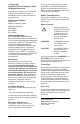
HP JetDirect Print Servers 10/100TX Link Jumpers (see Appendix B) HP J4100A Token Ring Data-Rate Switch HP J4105A HP J4100A for Fast Ethernet and IEEE 802.3u (10/ 100Base-TX, 10Base2) networks. An RJ-45 connector supports 10/100 Mbps network connections using unshielded twisted-pair cable. (For 100Base-TX networks, use Category 5 cable.) The BNC connector supports 10 Mbps operation through thin coaxial cables. HP J4105A for Token Ring (IEEE 802.
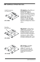
Quick Installation NOTE See chapter 2 for detailed information. 1. If you have a Token Ring card, Token Ring data-rate switch 4 Mbps Set the network Data-Rate switch to 16 Mbps (default) or 4 Mbps depending on your network. If you don't know the network data rate, ask your network administrator. 16 Mbps 2. Before installing the card, verify that your printer works. Print a test page or configuration plot. For instructions, see chapter 2 or refer to your printer manuals. 3.
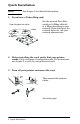
4. Verify that the card was installed correctly. Location of "I/O CARD READY" message on test page Print another test page (or configuration plot) and verify that the “I/O CARD READY” message appears. On the test page, the location of the “I/O CARD READY” message depends on your printer model. NOTE If other messages appear, see the troubleshooting sections of the HP JetDirect Print Server Administrators Guide.
6 Quick Installation
Contents Contents Quick Installation 1 The HP JetDirect Print Server Card Introduction . . . . . . . . . . . . . . . . . . . . . . . . . . . . . . . . . . . . . . The HP JetDirect Print Server Cards at a Glance . . . . . . . Supported Networks . . . . . . . . . . . . . . . . . . . . . . . . . . . . . . . What You Need for Installation . . . . . . . . . . . . . . . . . . . . . . 1-1 1-2 1-3 1-4 2 Installing the HP JetDirect Print Server Card Task 1.
4 Using the Control Panel To Configure HP JetDirect Cards in Large-Format Printers Introduction . . . . . . . . . . . . . . . . . . . . . . . . . . . . . . . . . . . . . . 4-1 Supported Network Protocols . . . . . . . . . . . . . . . . . . . . . . . . 4-2 Configuring Novell NetWare Frame Types . . . . . . . . . . . . . 4-6 Configuring TCP/IP Parameters . . . . . . . . . . . . . . . . . . . . . 4-9 Configuring Apple EtherTalk Phase Parameters (Ethernet Cards Only) . . . . . . . . . . . . . . . . . . . . . .
1 The HP JetDirect Print Server Card Introduction This guide shows you how to perform the hardware installation for the following printers: • HP Color LaserJet*, and Color LaserJet 5 Series* (5, 5M) • HP LaserJet 5Si Series* (5Si, 5Si MX, 5Si NX, 5Si Mopier) • HP LaserJet 5 Series* (5, 5M, 5N) • HP LaserJet 4Si Series* (4Si, 4Si MX) • HP LaserJet 4 Plus Series* (4 Plus, 4M Plus) • HP LaserJet 4 Series* (4, 4M) • HP LaserJet 4V Series* (4V, 4MV) • HP Professional Series* (2500C, 2500CM) • HP DeskJet 1200C S
The HP JetDirect Print Server Cards at a Glance J4100A J4105A Network Types Network Connections Supported Ethernet, IEEE 802.3 (10/100BaseTX, 10Base2) RJ-45 (unshielded twisted-pair cable), BNC (thin Ethernet coaxial cable) Network Types Network Connections Supported Token Ring, RJ-45 (unshielded IEEE 802.5 twisted-pair cable), (4 or 16 Mbps) DB 9 (type 1, 2 or 6 shielded twistedpair cable) Network Types Network Connections Supported Ethernet, IEEE 802.
Supported Networks Supported Network Protocols Supported Networks1 IPX/SPX and compatible Novell NetWare Microsoft Windows 95/98/NT/2000 J4100A J4105A J4106A EtherTalk AppleTalk J4100A J4106A 1 DLC/LLC Microsoft Windows NT Artisoft LANtastic2 J4100A J4105A J4106A TCP/IP Microsoft Windows 95/98/NT/2000 Novell NetWare 5 via NDPS LPD UNIX, including: Hewlett-Packard HP-UX, Sun Microsystems Solaris (Sun SPARCsystems only), Linux SCO UNIX2, IBM AIX2, HP MPE-iX2 J4100A J4105A J4106A Introduction A
What You Need for Installation • The appropriate HP JetDirect print server, documentation, and software. • A static-safe environment for handling the card. A grounding wrist strap or similar device is recommended. • Appropriate network cables and connectors for connecting the card to the network. • A small flat-blade screwdriver. Installing the card into the upper MIO slot of an HP LaserJet 4Si/4Si MX printer also requires a small Phillips-head screwdriver.
2 Installing the HP JetDirect Print Server Card Task 1. If you have a Token Ring card, set the Data-Rate switch (if necessary) Before installing a Token Ring card, you must set the data-rate switch to either 4 Mbit/second or 16 Mbit/second (factory default). The selected setting depends on the data-rate operation of your Token Ring network. 1. Locate the Data-Rate switch on the Token Ring print server card. 4 Mbit/s position Installing the HP JetDirect Print Server Card 2-1 Installation 16 Mbit/s 2 2.
Task 2. Before installing the card, verify the printer works The following pages show instructions for printing a self-test page or configuration plot to verify the printer is operating correctly. Locate and follow the instructions for your specific printer. If a self-test page or configuration plot does not print, see your printer manuals for troubleshooting procedures. HP LaserJet 5, 5M, and 5N printers 1. Turn on the printer. 2. Press [Menu] repeatedly until TEST MENU appears. 3.
HP LaserJet 5Si, 5Si MX, 5Si NX, 5Si Mopier printers 1. Turn on the printer and wait until a ready message is displayed. 2. Press [Menus] repeatedly until TEST MENU appears. 3. Press [Items] until PCL CONFIGURATION PAGE appears. 4. Press [Select*] to print the PCL configuration page.
HP Color LaserJet and Color LaserJet 5, 5M printers 1. Turn on the printer and wait until a ready message is displayed. 2. Switch the printer offline by pressing [On Line] to turn off the On Line light. 3. Press [Menu] repeatedly until the following appears: PCL TEST MENU PCL SELF TEST 4. Press [Enter]. A self-test page will print. .
HP LaserJet 4, 4M, 4 Plus, and 4M Plus printers 1. Turn on the printer and wait until the Ready light is lit. 2. Switch the printer offline by pressing [On Line] to turn off the On Line light. 3. Press [Menu] repeatedly until TEST MENU appears. 4. Press [Item] repeatedly until SELF TEST appears. 5. Press [Enter]. A self-test page will print.
HP LaserJet 4Si and 4Si MX printers 1. Turn on the printer and wait until the Ready light is lit. 2. Switch the printer offline by pressing [On Line] to turn off the On Line light. 3. Press [Menu] repeatedly until TEST MENU appears. 4. Press [Item] repeatedly until SELF TEST appears. 5. Press [Enter]. A self-test page will print.
HP LaserJet 4V and 4MV printers 1. Turn on the printer and wait until the Ready light is lit. 2. Switch the printer offline by pressing [On Line] to turn off the On Line light. 3. Press [Menu] repeatedly until TEST MENU appears. 4. Press [Item]. SELF TEST appears. 5. Press [Enter]. SELF TEST appears, followed by PRINTING TEST, and a self-test page will print.
HP 2500C/CM Professional Series and HP DesignJet ColorPro GA Printers 1. Turn on the printer and wait for READY to appear in the display panel. 2. Press [Menu] until SELF TEST MENU appears. 3. Press [Item] to display PRINT DIAGNOSTIC PAGE. 4. Press [Select]. A printer diagnostic page will print along with an HP JetDirect self-test page.
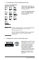
HP DeskJet 1600C, 1600CM, and 1600CN printers 1. Turn on the printer. 2. Press the blue button. A self-test page will print. Control Panel for HP DeskJet 1600C, 1600CM, and 1600CN 2 HP DeskJet 1200C and 1200 C/PS printers 1. Turn on the printer and wait until the Ready light is lit. 3. Hold [Shift] and press [Test]. A self-test page will print. Control Panel for HP DeskJet 1200C and 1200C/ PS printers Installing the HP JetDirect Print Server Card 2-9 Installation 2.
HP DesignJet 600 Series large-format printers 1. Turn on the printer and wait until the printer displays STATUS Ready to plot. 2. Press [Enter]. FULL MENUS Plot Mgmt → appears. 3. Press ↓ until FULL MENUS Utilities appears. 4. Press [Enter] again. UTILITIES
HP DesignJet 700, 750C, 750C Plus, 755CM, 2000CP, 2500CP, 3000CP, 3500CP large-format printers To print a DesignJet configuration page: 1. Turn on the printer and wait until STATUS Ready appears. 2. Press the two arrow keys simultaneously. To print a configuration plot for JetDirect: 1. Turn on the printer and wait until STATUS Ready appears. 2. Press [Enter]. FULL MENUS appears. 3. Press ↓ until FULL MENUS Utilities appears. 4. Press [Enter], then ↓ until Service Config appears. 5. Press [Enter].
HP CopyJet and CopyJet M color printer-copiers 1. Turn on the printer. 2. Press the [Test Menu] button. The control panel display shows - = Test page + = PCL fonts 3. Press [-] to print the Test Page.
Task 3. Insert the HP JetDirect print server card into the printer Locate the instructions for installing the card into your specific printer. To prevent electrostatic discharge (ESD) damage when installing the card, maintain frequent contact with any bare sheet metal surface on the printer. (See “What You Need for Installation” in chapter 1.) To install the card into the HP LaserJet 4, 4M, 4 Plus, 4M Plus, Color LaserJet, and Color LaserJet 5/5M printers 1. Turn off the printer and unplug the power cord.
Components face left for Color LaserJets (including 5/5M) 3. If the slot has a cover plate, remove it. 4. Insert the card. Align the card with the guide rails in the printer. 5. Press the card into the slot until firmly seated and tighten each thumbscrew a little at a time, alternating between each side until both screws are secure. 6. Connect the network cable to the card. 7. Connect the power cord and turn on the printer.
To install the card into the HP LaserJet 4V and 4MV printers 1. Turn off the printer and unplug the power cord. 2. Locate the HP modular I/O (MIO) slot at the back of the printer (see the figure below). 4. Insert the card. Align the card with the guide rails in the printer. 5. Press the card into the slot until the card is firmly seated. 6. Tighten each thumbscrew a little at a time, alternating between each side until both screws are secure. 7. Connect the network cable to the card. 8.
To install the card into the HP LaserJet 5, 5M, or 5N printers 1. Turn off the printer and unplug the power cord. 2. Locate the HP Modular Input/Output (MIO) slot at the back of the printer (see the figure below). Components face right for HP LaserJet 5, 5M, 5N 3. If the slot has a cover plate, remove it. 4. Insert the card. Align the card with the guide rails in the printer. 5.
The HP LaserJet 4Si Series and 5Si Series Printers Have Two Card Slots The HP LaserJet 4Si, 4Si MX, 5Si, 5Si MX, 5Si NX, and 5Si Mopier printers have two HP modular input/output (MIO) slots that enable you to run more than one type of network, such as Ethernet and Token Ring, by installing a card for each type of network. Note the following restrictions: • The use of two Ethernet cards in the same printer (which includes both 10Base-T or 100Base-TX cards) is not supported.
To install a card into the lower slot of the HP LaserJet 4Si Series, and either slot of the 5Si Series printers 1. Turn off the printer and unplug the power cord. 2. Locate the HP modular I/O (MIO) slots at the back of the printer.
3. Remove the cover plate. (Remember: use the lower slot for the 4Si or 4Si MX.) 4. Insert the card. Align the card with the guide rails in the printer. 5. Press the card into the slot until the card is firmly seated. 6. Tighten each thumbscrew a little at a time, alternating between each side until both of the screws are secure. 7. Connect the network cable. 8. Connect the power cord and turn on the printer.
To install a card into the upper MIO slot of the HP LaserJet 4Si and 4Si MX printers NOTE To use the upper slot of an HP LaserJet 4Si or 4Si MX printer, you must assemble two cards together and insert them both into the printer at the same time. To assemble the cards together, the card to be used in the upper slot must be fitted with a custom cover plate. Custom cover plates must be ordered from Hewlett-Packard: •C2009-60111 (for HP J4105A or J4106A) 1. Turn off the printer and unplug the power cord. 2.
4. For the HP JetDirect card that will be installed into the upper slot, remove the front plate by removing the two side screws (A). • If your HP JetDirect card is a Token Ring card, also remove the mounting screws (B) from the front plate. • The front plate should separate from the card. Save this front plate for future use, if desired. 2 Remove faceplate from card Custom cover plate for Token Ring card Installing the HP JetDirect Print Server Card 2-21 Installation 5.
6. Compare the HP JetDirect card’s front plate with the custom cover plate. Peel off the appropriate part of the label on the customized cover plate to match the holes punched out on the HP JetDirect card’s front plate: • If you are installing an HP J4106A JetDirect card (RJ-45 port only), expose that hole in the custom cover plate by peeling off the RJ-45 portion of the label. • For an HP J4105A JetDirect card, peel off the DB-9 and RJ-45 portions of the label. 7.
8. With the components facing up, assemble the two cards together. The card that will be installed into the upper slot (with custom cover plate) will be to the right. Secure the cards by tightening the spring-loaded thumbscrews (C). Connect cards with customized plate at right 2 9. Attach the plastic retaining clip (D) to the card assembly, matching the small holes in the two cards.
10. With the components facing the left edge of the printer, slide the card assembly into the printer. Align the top and bottom of the assembly with the top and bottom guide rails located inside the printer. Press the cards into the slot until the cards are firmly seated. CAUTION The assembly must fit into the guide rails correctly. Failure to install the assembly correctly may cause damage to the formatter board or to the MIO assembly. Insertion of two cards into HP LaserJet 4Si/4SiMX 11.
NOTE For the HP J4100A JetDirect card (RJ-45 and BNC), you can connect to one of the Ethernet ports (only one Ethernet port is active at a time). For the HP J4105A JetDirect card (RJ-45 and DB9, you can connect to only one Token Ring port. To install the card into HP 2500C/CM Professional Series and HP DesignJet ColorPro GA Printers 1. Turn the printer off and unplug the power cord. 2. Locate the HP modular I/O (MIO) slot at the back of the printer. 2 4. Insert the card.
NOTE For the HP J4100A JetDirect card (RJ-45 and BNC), you can connect to one of the Ethernet ports (only one Ethernet port is active at a time). For the HP J4105A JetDirect card (RJ-45 and DB9), you can connect to only one Token Ring port. 7. Connect the power cord. 8. Turn on the power switch. To install the card into the HP DeskJet 1200C, 1200C/PS, 1600C, 1600CM, and 1600CN printers 1. Turn off the printer and unplug the power cord. 2.
4. Insert the card. Align the card with the guide rails in the printer. 5. Press the card into the slot until firmly seated and tighten each thumbscrew a little at a time, alternating between each side until both screws are secure. 6. Connect the network cable to the card. 7. Connect the power cord. 8. For the HP DeskJet 1200C, 1600C, 1600CM and 1600CN printers, turn on the power switch.
To install the card into the HP DesignJet 600 Series, 700 Series, 2000/2500/3000/3500 Series large-format printers 1. Turn off the printer but leave the power cord plugged in. 2. Locate the HP modular I/O (MIO) slot located at the back of the printer (see the appropriate figure below).
Components face toward back, DesignJet 700/ 2000/2500/3000/3500 Series 5. Press the card into the slot until the card is firmly seated. 6. Tighten each thumbscrew a little at a time, alternating between each side until both screws are secure. 7. Connect the network cable to the card and turn on the printer. NOTE For the HP J4100A JetDirect card (RJ-45 and BNC), you can connect to one of the Ethernet ports (only one Ethernet port is active at a time).
To install the card into the HP CopyJet and CopyJet M color printer-copiers 1. Turn off the printer and unplug the power cord. 2. Locate the HP modular I/O (MIO) slot at the back of the printer (see the figure below). Components face right for CopyJet and CopyJet M printers 3. If the slot has a cover plate, remove it. 4. Insert the card. Align the card with the guide rails in the printer. 5. Press the card into the slot until the card is firmly seated. 6.
Task 4. Verify the card was installed correctly 1. Print a new self-test page or configuration page. 2. Using the diagram on the following page as a guide, locate the phrase “I/O CARD READY” on the self-test page.
Location of I/O CARD READY message on self-test pages 3. For more information about this section of the self-test page, see your HP JetDirect Administrators Guide on the HP JetDirect CD-ROM. 4. If the I/O CARD READY message appears, the card has been installed successfully. See “What To Do Next”. If the message does not appear, check that you have: • installed the card correctly • reconnected the printer/plotter to the network • turned the printer off and on.
NOTE For HP J4100A 10/100Base-TX cards, see appendix B in this manual for special troubleshooting information. If the message still does not appear, contact HP Customer Care (see the HP JetDirect 400N Quick Setup Guide for phone numbers or Web access). What To Do Next You are now ready to configure the card. You can configure the card in various ways, including: • Using HP JetDirect software on the HP JetDirect CD-ROM, and other network utilities, for card and printer configuration.
2-34 Installing the HP JetDirect Print Server Card
3 Using the Control Panel To Configure HP JetDirect Cards in Printers Introduction If you have an HP DesignJet large-format printer (except DesignJet ColorPro GA), go to Chapter 4. The printers listed below have control panels that let you configure certain network parameters manually.
Enabling and Disabling Network Protocols When you first install the card from the factory, all supported network protocols are enabled (or turned on) when you turn the printer on. The card provides automatic network switching between network protocols for printers that do not support this function. If you reconfigure the card—for example, you disable a network protocol—your configuration is saved on the card and is maintained even after the printer is turned off.
To enable or disable network protocols NOTE For HP 2500C/CM Professional Series and DesignJet ColorPro GA printers, see the “HP 2500C/CM Professional Series and DesignJet ColorPro GA Control Panel” instructions at the end of this chapter. 1. Take the printer offline by pressing [On Line] or [Go] to indicate offline. 2.
8. Press [Item] to continue to the next protocol. Example: To enable the DLC/LLC protocol, press [Item] until the control panel displays either DLC/LLC=ON* or DLC/LLC=OFF*. If DLC/LLC=ON* is displayed, press [Item] to retain that protocol and continue to the next protocol. This turns on the DLC/LLC protocol. If DLC/LLC=OFF* is displayed, press [+] and then press [Select] or [Enter] to change the protocol. Then press [Item] again to continue to the next protocol. 9.
Novell NetWare Frame Types on an HP JetDirect Token Ring Card Frame Type Description AUTO (default) Automatically senses and limits the frame type to the one detected. TR_8022 Limits the frame type to IPX over IEEE 802.2 with IEEE 802.5 frames. All others will be counted and discarded. TR_SNAP Limits the frame type to IPX over SNAP with IEEE 802.5 frames. All others will be counted and discarded.
3. Press [Item] until CFG NETWORK=NO* appears. 4. Change the message to CFG NETWORK=YES* using the following buttons: 5 Series and 5Si Series printers Press [+], then [Select] Other printers Press [+], then [Enter] 5. Press [Item] until CFG IPX/SPX=NO* appears. 6. Change this to CFG IPX/SPX=YES* by pressing [+], and then pressing [Select] or [Enter] depending on your printer model. 7. Press [Item] until FRAME=* appears. • The asterisk (*) indicates the active frame type selected.
Configuring Novell NetWare Source Routing (Token Ring Cards Only) You can select the method for Novell NetWare Token Ring source routing from the control panel. The possible routing methods are: • AUTO (default): Source routing is enabled if necessary. • OFF: All packets are sent without source routing—packets are received only if they originate from the same ring. • SINGLE R: All packets are sent with source routing. The Single Route method is used for broadcasts and when the route is unknown.
4Si Series printers (select the card slot being configured) MIO MENU 1 or MIO MENU 2 5Si Series printers (select the card slot being configured) HP MIO 1 MENU or HP MIO 2 MENU 5 Series printers HP MIO MENU 3. Press [Item] until CFG NETWORK=NO* appears. 4. Change the message to CFG NETWORK=YES* using the following buttons: 5 Series and 5Si Series printers Press [+], then [Select] Other printers Press [+], then [Enter] 5. Press [Item] until CFG IPX/SPX=NO* appears. 6.
Configuring TCP/IP Parameters Using the control panel of your printer, you can manually configure these TCP/IP parameters: • You can configure BOOTP, which automatically downloads configuration data over the network (this is the default setting), or • You can enter these parameters individually: • IP address (4 bytes) • Subnet mask (4 bytes) • Syslog server IP address (4 bytes) • Default gateway (4 bytes) • TCP connection timeout (in seconds) A valid IP address is required for proper operation of the car
To configure TCP/IP parameters NOTE For HP 2500C/CM Professional Series and DesignJet ColorPro GA printers, see the “HP 2500C/CM Professional Series and DesignJet ColorPro GA Control Panel” instructions at the end of this chapter. If you have not already done so, enable TCP/IP (TCP/IP=ON*) by following the instructions described in “To enable or disable network protocols” in this chapter. CAUTION Enter data carefully.
6. Change this to CFG TCP/IP=YES* by pressing [+], and then pressing [Select] or [Enter] depending on your printer model. 7. Press [Item] until BOOTP=YES* or BOOTP=NO* appears. • The asterisk (*) indicates the active selection. • To change the BOOTP= setting, press [+]. Then press [Select] or [Enter] depending on your printer model. Be sure “*” appears alongside your selection. If BOOTP=YES*, the printer is configured to retrieve its TCP/IP parameters over the network using BOOTP or DHCP.
Configuring Apple EtherTalk Phase Parameters (Ethernet Cards Only) You can configure Apple EtherTalk parameters if the Apple EtherTalk protocol is enabled (ETALK=ON*), and the PostScript printer language is enabled. To ensure the PostScript printer language is enabled, check the Configuration Menu (for 5Si Series printers) or the JOB MENU (for other printers). PERSONALTY=PS* or PERSONALTY=AUTO* should be set.
4. Change the message to CFG NETWORK=YES* using the following buttons: 5 Series and 5Si Series printers Press [+], then [Select] Other printers Press [+], then [Enter] 5. Press [Item] until CFG ETALK=NO* appears. 6. Change this to CFG ETALK=YES* by pressing [+], and then pressing [Select] or [Enter] depending on your printer model. 7. Press [Item]. ETALK PHASE=1* or ETALK PHASE=2* appears on the control panel. • The asterisk (*) indicates the active phase setting.
Configuring the Timeout for End-of-Job Sensing When installed in an HP LaserJet 4 or 4M printer, the HP JetDirect card provides a Job Timeout parameter. For networks with multiple network protocols, the Job Timeout parameter specifies the time that the HP JetDirect card remains connected to an active network protocol even though it is idle. After that time, the card allows access by another protocol. To set the JOB TIMEOUT parameter for HP LaserJet 4, 4M printers 1.
HP 2500C/CM Professional Series and DesignJet ColorPro GA Control Panel To enable or disable network protocols 1. Take the printer offline by pressing the online/offline button . 2. Press [Menu] repeatedly until MIO MENU appears. 3. Press [Item]. CONFIGURE MIO appears. 4. Press [Select]. CFG NETWORK NO appears. This message does not mean that you must reconfigure your protocol. It means only that you do not intend to access the network configuration menus. 5. Press [Value] to display CFG NETWORK YES .
To configure a NetWare frame type If you have not already done so, enable the IPX/SPX protocol (IPX/ SPX ON) by following the instructions above. 1. Take the printer offline by press the online/offline button . 2. Press [Menu] repeatedly until MIO MENU appears. 3. Press [Item]. CONFIGURE MIO appears. 4. Press [Select]. CFG NETWORK NO appears. This message does not mean that you must reconfigure your protocol. It means only that you do not intend to access the network configuration menus. 5.
4. Press [Select]. CFG NETWORK NO appears. This message does not mean that you must reconfigure your protocol. It means only that you do not intend to access the network configuration menus. 5. Press [Value] to display CFG NETWORK YES . Then press [Select]. 6. Press [Item] until CFG IPX/SPX NO appears. 7. Press [Value] to display CFG IPX/SPX YES. Then press [Select]. 8. Press [Item] until SRC RT appears.
7. Change this to CFG TCP/IP YES by pressing [Value]. Then press [Select]. 8. Press [Item] until BOOTP YES or BOOTP NO appears. 9. To change the BOOTP setting, press [Value]. Then press [Select]. • If BOOTP YES is set, the printer is configured to retrieve its TCP/IP parameters over the network using BOOTP or DHCP. No other TCP/IP prompts will be displayed on the printer’s control panel. • If BOOTP NO is set, the printer is configured to accept TCP/ IP parameters from the printer’s control panel.
To configure EtherTalk parameters To ensure the PostScript printer language is enabled, check the CONFIGURATION MENU. PERSONALITY=PS or PERSONALITY=AUTO should be set. If you haven’t already done so, enable EtherTalk (ETALK ON) by following the instructions described above. 1. Take the printer offline by press the online/offline button . 2. Press [Menu] repeatedly until MIO MENU appears. 3. Press [Item]. CONFIGURE MIO appears. 4. Press [Select]. CFG NETWORK NO appears.
3-20 Using the Control Panel for Printers
4 Using the Control Panel To Configure HP JetDirect Cards in Large-Format Printers Introduction If you have an HP DesignJet printer listed below, you can manually configure certain network parameters using the printer control panel: • • • • • • • • DesignJet 3000CP/3500CP DesignJet 2000CP/2500CP DesignJet 755CM DesignJet 750C Plus DesignJet 750C DesignJet 700 DesignJet 650C DesignJet 600 NOTE For HP DesignJet ColorPro GA printers, see chapter 3.
Once you have configured these parameters using the control panel, you still need to install the appropriate print server software to complete the configuration process. Refer to your HP JetDirect software installation guide for instructions. Supported Network Protocols When you first install the card from the factory, all supported network protocols are enabled (or turned on) when you turn the printer on.
To enable or disable network protocols on the DesignJet 600 Series printers 1. Turn on the printer. 2. Verify that the printer displays STATUS and Ready to plot. 3. Press [Enter] until MENUS (FULL MENUS on the 650C printer) and Plot mgmt → appear. 4. Press ↑ repeatedly until MENUS and I/O setup→ appear. 5. Press [Enter] to access the MIO slot. I/O SETUP and Modular→ appear. 6. Press [Enter]. MIO SETUP and CFG NETWORK=NO→ appear. 7.
NOTE You will see CFG NETWORK=NO whenever you enter the JetDirect configuration menu. The message only indicates that you do not intend to access the configuration menu. It does not mean that you must reconfigure your protocol. To continue manually configuring protocol parameters, go to the appropriate sections that follow. To complete the print server configuration, see the HP JetDirect software installation guide included with the product.
6. Press ↓ to change NO* to YES, then press [Enter] to display CFG NETWORK=YES. 7. At the CFG NETWORK=YES message, press ↑ repeatedly to scroll through the configuration options. a. To change a network protocol setting (enable or disable), press [Enter], ↓, [Enter]. b. To configure network protocol parameters press [Enter], ↓ to select YES, then press [Enter] again. To continue configuring protocol parameters, go to the appropriate sections that follow. 8. Press [Previous] and return to STATUS Ready. 9.
Configuring Novell NetWare Frame Types You can set the NetWare frame types if the NetWare protocol is enabled (NETWORK=NOVELL→ or NETWORK=AUTO→ was displayed on your control panel). You can configure one of the following frametype settings: Novell NetWare Frame Types on an HP JetDirect Ethernet Card Frame Type Description AUTO (default) Automatically senses and limits the frame type to the one detected. EN_8023 Limit frame types to IPX over IEEE 802.3 frames. All others will be counted and discarded.
To configure a NetWare frame type If you haven't already done so, enable Novell NetWare by following the instructions described in “To enable or disable network protocols” in this chapter. For the 600 Series Printers 1. Access the configuration menu (see “To enable or disable network protocols” in this chapter). 2. Press ↑ until Novell→ or Auto→ appears. 3. Press ↑. MIO SETUP and FRAME=→ appear. 4. To maintain the current frame type, press ↑. 5.
Configuring Novell NetWare Source Routing (Token Ring Card Only) You can select the method for Novell NetWare source routing from the control panel. The possible routing methods are: • AUTO (default): Source routing will be enabled on a packetby-packet basis. • OFF: All packets are sent without source routing—that is, packets must be from the same ring. • SINGLE R: Source routing used for all packets sent. The Single Route method is used for broadcasts and when the route is unknown.
For the 700/2000/2500/3000/3500 Series Printers 1. Access the configuration menu (see “To enable or disable network protocols” in this chapter). 2. From the CFG IPX/SPX=NO→ menu item, press [Enter], ↓, [Enter] to display CFG IPX/SPX=YES→ . 3. Press ↑ repeatedly until SRC RT=AUTO appears. 4. To change source routing, press [Enter] and ↓ until the source routing that you want appears. 5. To save the new source routing setting, press [Enter]. (Press [Enter] again to verify your selection with “*”.) 6.
NOTE For DHCP (Dynamic Host Configuration Protocol) operation, BOOTP must be enabled. If an IP address is configured through DHCP and is subsequently changed through the control panel, the DHCP assigned address is released. If a printer is configured through DHCP, and you manually change the subnet mask or default gateway through the control panel, you should also change the IP address.
5. Press ↑ to configure each TCP/IP parameter. For the first parameter, MIO SETUP and IP BYTE 1=→ appear. 6. To maintain the current value, press ↑. 7. To change the value, proceed as follows: a. Press [Enter] to display the current value. b. Press ↑ until the value that you want appears. c. Press [Enter] to save the new value. MIO SETUP and IP BYTE 1=→ appear. d. Press ↑ to continue. 8. Configure the remaining bytes of the IP address in the same manner.
• If you select BOOTP=NO→, the printer is configured to accept TCP/IP parameters from the control panel. Continue with step 4. 4. If you selected BOOTP=NO→, press ↑ to configure each TCP/IP parameter. For example, to configure the IP address: a. Press ↑ until IP BYTE=0 is displayed. Press [Enter]. b. Press ↑ or ↓ to select the number (0-255) for that byte, then press [Enter]. c. Press ↑ to select the next byte. d. Continue the same process until all bytes are entered.
Configuring Apple EtherTalk Phase Parameters (Ethernet Cards Only) NOTE EtherTalk is supported by HP DesignJet 650C, Series 700, and 2500CP series printers with PostScript modules installed. You can set Apple EtherTalk parameters if the Apple EtherTalk protocol and the PostScript printer language are enabled (Lang=Postscript→).
For the 700/2000/2500/3000/3500 Series Printers 1. Access the configuration menu (see “To enable or disable network protocols” in this chapter). 2. From the CFG ETALK=NO→ menu item, press [Enter], ↓, [Enter] to display CFG ETALK=YES→ . 3. Press ↑ to display the current phase parameter. To change the setting, press [Enter], ↓, [Enter]. 4. To save the configuration, print a configuration plot by pressing the two arrow keys simultaneously. Your printer configuration is now active.
6. To access the network configuration menu, press [Enter] to display CFG NETWORK and NO *. 7. Press ↑ to display: CFG NETWORK and YES. 8. Press [Enter]. MIO SETUP and CFG NETWORK=YES→ appear. You can now access the network configuration menu. 9. Press ↑ repeatedly until MIO SETUP and JOB TIMEOUT= → appear. 10. To maintain the current value, press ↑. 11. To change value, proceed as follows: a. Press [Enter] to display the current value. b.
4-16 Control Panel for Large-Format Printers
Specifications for HP J4100A, J4105A, and J4106A Print Server Cards Electrical 0.60 A @ 5 V typical; 1.25 A @ 5 V maximum Environmental Operating Non-Operating Temperature 0°C to 55°C (32°F to 131°F) -40°C to 70°C (-40°F to 158°F) Relative humidity: (non-condensing) 15% to 95% at 40°C (104°F) 15% to 90% at 65°C (149°F) Maximum altitude 4.6 km (15,000 ft) 4.
Regulatory Statements FCC Statements General Information This device complies with Part 15 of the FCC Rules. Operation is subject to the following two conditions: (1) This device may not cause interference, and (2) this device must accept any interference received, including interference that may cause undesired operation. Pursuant to Part 15.
• European Community When used with Ethernet, IEEE 802.3/802.3u 10/100Base-TX, or Token Ring configurations, this equipment complies with EN55022 Class A. NOTE This is a class A product. In a domestic environment, this product may cause radio interference, in which case the user may be required to take adequate measures. Specifications and Regulatory Statements A-3 Specifications Connect the equipment into an outlet on a circuit different from that to which the receiver is connected.
Declaration of Conformity The following Declaration of Conformity complies with ISO/IEC Guide 22 and EN45014. It identifies the product, the manufacturer’s name and address, and the applicable specifications that are recognized in the European community.
Canada This equipment complies with Canadian EMC Class-A requirements. Japan: VCCI Class A. RRL Statement (Korea). Taiwan Class A. Specifications and Regulatory Statements A-5 Specifications This equipment complies with Australian EMC requirements.
Chinese Safety Statement A-6 Specifications and Regulatory Statements
B HP J4100A 10/100Base-TX Print Server Supported Links If the card is not able to connect to the network through autonegotiation, you can manually set the link operating mode using link configuration jumpers on the card. Link-Speed LEDs The HP J4100A print server provides 2 light-emitting diodes (LEDs) near the RJ-45 connector. These LEDs indicate the operating link speed of the print server, either 10 or 100 Mbps.
Link Configuration Jumper Settings The HP J4100A JetDirect 10/100Base-TX card provides link configuration jumpers that may be manually set if autonegotiation is not able to connect the card to the network. You can set the link operation for 100 Mbps Full Duplex, 100 Mbps Half Duplex, or 10 Mbps Half Duplex. (Note that reconfiguration of the hub or switch port may also be required.) Link Configuration jumpers For jumper setting definitions, refer to the following illustration.
Link Troubleshooting If the HP J4100A JetDirect 10/100Base-TX print server does not successfully connect to the network, both LEDs will be off and a “LOSS OF CARRIER ERROR” will be indicated in the MIO section of the HP JetDirect self-test page. NOTE • Verify cabling connections. • At the network device (such as a switching hub) that connects the print server to the network, configure the port for halfduplex operation. Then power-cycle the printer.
B-4 HP J4100A 10/100Base-TX Print Server
©Copyright 2000 Hewlett-Packard Company 2/2000 Manual Part Number 5969-3587 *5969-3587*