HP UPS Management Module User Guide Part Number 435656-004 January 2010 (Fourth Edition)
© Copyright 2007, 2010 Hewlett-Packard Development Company, L.P. The information contained herein is subject to change without notice. The only warranties for HP products and services are set forth in the express warranty statements accompanying such products and services. Nothing herein should be construed as constituting an additional warranty. HP shall not be liable for technical or editorial errors or omissions contained herein. Confidential computer software.
Contents Overview ..................................................................................................................................... 7 Introduction ................................................................................................................................................. 7 Features ......................................................................................................................................................
Uninstalling components from HP-UX systems ................................................................................................ 41 HP UPS Management Module web interface .................................................................................. 42 HP UPS Management Module web interface overview ................................................................................... 42 Accessing the web interface ................................................................................
Agent does not install on Red Hat Itanium® .................................................................................................. 91 Attached device communication errors appear .............................................................................................. 91 Attached device did not shut down gracefully ............................................................................................... 91 Battery Test did not run ........................................................
Technical support ...................................................................................................................... 103 Before you contact HP .............................................................................................................................. 103 HP contact information .............................................................................................................................. 103 Regulatory compliance notices .................................
Overview Introduction The HP UPS Management Module enables you to monitor, manage, and control power environments of up to five devices through the serial connectors located on the front of the management module. Multiple devices can monitor the UPS over the network connection. The management module can be configured to send alert traps to HP Systems Insight Manager and other SNMP management programs or used as a stand-alone management system.
HP UPS Power Protection Agent overview The HP UPS Power Protection Agent runs on a local or network server and allows the management module to gracefully shut down the operating system of that server and optionally run a script during power failure. Install the agent on any machine that is powered by the UPS and any machine that the management module uses to initiate a command.
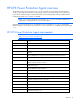
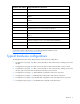
Hardware and software Suggested minimum requirements VMware ESX Server 3.0.3¹ VMware ESX Server 2.5.
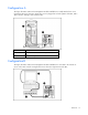
Configuration A This figure illustrates a UPS with a management module installed that is serially attached to a server running the UPS Power Protection Agent. The server is plugged into a load segment of the UPS, and is able to monitor, manage, and control the UPS. Item Description 1 Server with UPS Power Protection Agent installed 2 UPS with management module installed Configuration B This figure illustrates a UPS with a management module installed that is connected to the network.
Item Description 1 Server with UPS Power Protection Agent installed 2 Network 3 UPS with management module installed Configuration C This figure illustrates a UPS with a management module installed that is serially attached to a server running the UPS Power Protection Agent. The server is plugged into a load segment of the UPS, and is able to monitor, manage, and control the UPS.
Configuration D This figure illustrates a redundant configuration with serial connections. This configuration only applies to servers with multiple native serial ports.
Configuration E This figure illustrates a redundant configuration with network connections.
Configuration F This figure illustrates a redundant configuration with serial and network connections.
Configuration G This figure illustrates a redundant configuration with dual subnet. Item Description 1 Subnet A 2 UPS A 3 Server 4 Subnet B 5 UPS B Power connection Communication path Web interface requirements The following table lists the minimum requirements necessary to operate the web interface. Software Browser Web browser on a client • Microsoft® Internet Explorer 6.0 with Service Pack 1 (32-bit only) • • Microsoft® Internet Explorer 7.
Software Browser resolution high color (maximize browser window for optimal display) Quick installation and setup overview 1. Install the HP UPS Management Module in the UPS ("Installing the HP UPS Management Module" on page 18). 2. Install and configure the HP Power Protection Agents to communicate with the management module ("Installing the HP UPS Power Protection Agent" on page 26). 3. Access the HP UPS Management Module web interface ("Accessing the web interface" on page 42). 4.
Component identification Front panel Item Description 1 Serial device connectors 2 Environmental connector (for future use) 3 Power LED 4 Error LED 5 Reset button 6 Network connector 7 Config/Pass-Thru connector Component identification 17
Installing the HP UPS Management Module Required tools No. 2 Phillips screwdriver Installing the management module NOTE: It is not necessary to power down the UPS before installing the management module. 1. Disconnect the communications cable from the option card. 2. Remove the two screws securing the option card or cover plate and slide the card or plate out.
3. Install the management module along the alignment channels in the option slot. 4. If the UPS is powered up, you can be sure that the management module is seated properly and receiving power by verifying that the Power LED is illuminated solid green. 5. Secure the management module using the two screws you removed in step 2.
Checking the Error LED If the Error LED illuminates red or flashes red, see the "Troubleshooting (on page 91)" section for more information. Connecting the network cable Connect a standard Ethernet cable between the network connector on the management module and a network jack. This connection is used to access the management module remotely through telnet or the web interface.
Connecting the configuration cable 1. Connect a DB-9 to RJ-45 adapter to a serial connector on the host computer. 2. Connect one end of an RJ-45 cable to the RJ-45 connector on the adapter. 3. Connect the other end of the RJ-45 cable to the Config/Pass-Thru connector on the management module. This connection is used to configure and access the management module locally through a terminal emulation program.
1. On the host computer, click Start, and select Programs>Accessories>Communications>HyperTerminal. The Connection Description window appears. 2. Enter a description, select an icon for the connection, and then click OK. The Connect To window appears. 3. Select the serial connector on the host computer to which the DB-9 to RJ-45 adapter is attached, and then click OK. The COM Properties window appears. 4. Select the following parameter values, and then click OK.
Use the HP UPS Management Module Service Menu to configure the minimum settings required to access the management module remotely using telnet or the web interface. You can configure other settings using this utility in conjunction with a terminal emulation program or a telnet connection. IMPORTANT: The IP address assigned to the management module must be fixed. If the IP address changes: • The UPS Power Protection Agent loses communication with the management module.
2. Connect one end of a network cable to the RJ-45 connector on the adapter. 3. Connect the other end of the network cable to a serial device connector on the management module. Note the connector number on the management module to which the device is connected. 4. Connect the device to a UPS load segment receptacle using the device input power cord or a jumper cable.
5. Press the Reset button on the management module front panel.
Installing the HP UPS Power Protection Agent Installation overview Install the UPS Power Protection Agent on any machine that is powered by the UPS and any machine that the management module uses to initiate a command. There are three installation options: • GUI installation—A series of dialog boxes and prompts guide you through the installation process. • Non-GUI installation—A series of commands are necessary to complete the installation.
IMPORTANT: The agent communicates with the management module over the network using port number 3573. Newer Windows operating systems might require that you manually enable inbound and outbound communications on port 3573. See your operating system documentation for more information. NOTE: You might need to reboot after installing the agent on Windows®. Installing the agent using the GUI method 1. Insert the HP Infrastructure Management Pack CD into the CD-ROM drive of the computer.
5. Read the license agreement, select I accept the terms in the license agreement, and then click Next. The Customer Information screen appears.
6. Enter your customer information, and then click Next. The Choose Destination Location screen appears.
7. Click Next to install the agent in the default folder that is displayed. To specify a different folder, click Change, navigate to the appropriate folder, and then click Next. The Ready to Install the Program screen appears.
8. Click Install. The wizard installs the software.
9. Click Finish to complete the install wizard and continue with the configuration process. NOTE: It might take a moment for the configuration screen to appear. If there are open windows on the desktop, you might need to minimize the windows to view the configuration screen. 10. Enter the valid host name, IP address, or communications port of the management module in the Management Server 1 field.
12. Click Finish to close the configurator. The service starts automatically. Wait until the system tray icon displays a green check mark begin using the software. to NOTE: An icon in the Windows® system tray shows the status of the management module. It appears if the might take a few moments for the icon to change. A green check mark management module is communicating with the agent without errors. If the service has stopped, a blue hexagon icon appears.
• Change any items that should be unique, such as the Management Server IP address, through the normal operation of the software. To install the agent using the silent installation method: 1. Create a temporary directory. 2. Copy the following files into the temporary directory you just created: 3. o DevManRA.ini—During an assisted install, this file is landed in the same folder in which the agent is installed. o Setup.
• Select Configure HP UPS Management Module from the HP UPS Management Module option in the Start Programs menu. Installing the agent on Linux operating systems The UPS Power Protection Agent can be installed using an installation script or the silent installation option on any supported Linux operating system. IMPORTANT: To ensure your system has the minimum requirements needed to run the agent, see "UPS Power Protection Agent requirements ("HP UPS Power Protection Agent requirements" on page 8).
The installer launches a separate configuration program. The script displays: Please enter a server to allow connections from. 2. Enter the IP address of the management module or the path to the serial device. This configuration ensures that only that particular management module executes commands and operating system shutdowns on the computer running the agent. The script displays: Please enter a second server to allow connections from. 3.
• Change any items that should be unique, such as the Management Server IP address, through the normal operation of the software. To install the agent using the silent installation method: 1. Create a temporary directory. 2. Copy the following files into the temporary directory you just created: 3. o DevManRA.ini—During an assisted install, this file is landed in the same folder in which the agent is installed. o EULA.
o Edit the /etc/sysconfig/boot file and change RUN_PARALLEL="yes" to RUN_PARALLEL="no" to remove parallel script execution. -or- o Edit the /etc/init.d/.depend.start file and add DevMan: network at the end of the file to add parallel information for DevMan. Reconfiguring the agent on Linux operating systems To configure the management module IP address or serial path for Red Hat Linux, run /etc/rc.d/init.d/DevMan setup.
IMPORTANT: If you are configuring redundant management modules, do not enter an asterisk to allow any server to connect to the management module. If you do not want to configure a second connection, enter None. Installing the agent locally or remotely using the SAM method 1. From a remote machine, enter sam at the command line prompt. 2. Click Software Management. 3. Click Install Software to Local Host. 4. Change the Source Depot Path to a fully qualified path and depot name. 5.
• Change any items that should be unique, such as the Management Server IP address, through the normal operation of the software. To install the agent on a system running HP-UX using the silent installation method: 1. Create a temporary directory. 2. Copy the following files into the temporary directory you just created: 3. o DevManRA.ini—During an assisted install, this file is landed in the same folder in which the agent is installed.
2. Open Add/Remove Programs. 3. Select UPS Power Protection Agent, and then click Change/Remove. The uninstall wizard launches. Select Remove Choice, and then click Next. 4. Follow the prompts in the uninstall wizard to uninstall the software. NOTE: Some files might remain following the uninstallation and can be removed manually. Uninstalling components from Linux systems Execute the uninstall script (./Uninstall). NOTE: Some files might remain following the uninstallation and can be removed manually.
HP UPS Management Module web interface HP UPS Management Module web interface overview The web interface graphically displays various measurements and warning and alarm messages from the management module. Also, system values and power fail settings can be configured through the web interface and sent to the management module.
System tray icon To access the web interface through the system tray in Windows®: 1. Right-click the software system tray icon on a computer with the UPS Power Protection Agent installed to display a context menu. 2. Click Connect to access the software. NOTE: If the unavailable. Icon icon appears, the Connect option is unavailable because the service is Status Software service/daemon is running. The agent and management module are communicating. UPS status is normal.
For instructions on changing the password, see "My Account menu (on page 59)." Admin session logins, logouts, and terminations are recorded in the Event Log menu (on page 56). The console session timeout length can be modified in the Remote Access tab (on page 66). The following is a list of recommended password guidelines. • Passwords should not be shared with others. • Passwords should be limited to one or two people, if shared with others.
Establishing a secure session for Internet Explorer The first time you browse to the management module, the Secure Session screen appears. To ensure a secure connection, verify that you are browsing to the desired management module: 1. Click View Certificate. 2. Verify that the name in the Issued To field is the name of your management module. 3. Perform any other steps necessary to verify the identity of the management module.
Establishing a secure session for Firefox The first time you browse to the management module, the Secure Session screen appears. To ensure a secure connection, verify that you are browsing to the desired management module: 1. Click Examine Certificate. 2. Verify that the name in the Issued To field is the name or IP address of your management module. 3. Perform any other steps necessary to verify the identity of the management module. 4.
• Main frame—Contains the various interface screens based on the menu option selected in the left navigation frame. Home tab Menu options listed under the Home tab include: • Overview menu (on page 47) • Alarms menu (on page 49) • Identification menu (on page 51) • Parameters menu (on page 52) • Manual Control menu (on page 55) Overview menu Click Overview in the left navigation frame to display the Overview screen. This screen displays overall views of the UPS status.
The following example is for a single module UPS. The following example is for a 3 phase individual or parallel UPS. Battery, Input, and Output information is displayed on the right side of the screen. A status icon indicates the current status of each parameter.
Input Voltage, Output Voltage, and Load information is displayed graphically on the left side of the screen. The color on each meter represents the current state of the UPS. Color Status Green Normal Yellow Warning Red Critical Click Help to view online help. Alarms menu Click Alarms in the left navigation frame to display the Alarms screen. This screen displays the alarms for the UPS. The alarms are listed in alphabetical order.
The following example is for a 3 phase individual or parallel UPS. Click the UPS tabs to view detailed information for each of the sub units in the parallel system. The parallel system can contain up to six sub units. Click Refresh to refresh the screen, or click Help to view online help.
Identification menu Click Identification in the left navigation frame to display the Identification screen. This screen contains contact information for the management module and specific device information about the management module and the UPS. The following example is for a single module UPS.
The following example is for a 3 phase individual or parallel UPS. Click the UPS tabs to view detailed information for each of the sub units in the parallel system. The parallel system can contain up to six sub units. Enter the system name and contact information using the System Information tab (on page 63) on the Network Management screen. Click Refresh to refresh the screen, or click Help to view online help.
NOTE: Depending on the specific UPS model, this screen will vary. The following example is for a single module UPS.
The following example is for a 3 phase individual or parallel UPS. Click the UPS tabs to view detailed information for each of the sub units in the parallel system. The parallel system can contain up to six sub units.
Click Help to view online help. Manual Control menu Click Manual Control in the left navigation frame to display the Manual Control screen. This screen contains manual commands such as Initiate Battery Test and Restart Management Module. NOTE: Depending on the specific UPS model, this screen will vary. The Initiate Battery Test option is not available for all UPSs. To initiate a UPS battery test: CAUTION: Selecting this option might result in an ungraceful shutdown.
Logs tab Menu options listed under the Logs tab include: • Event Log menu (on page 56) • Application Log menu (on page 58) Event Log menu Click Event Log in the left navigation frame to display the Event Log screen. This screen displays a log of the events that have occurred on the UPS, such as the UPS switching to battery power. The following example is for a single module UPS.
The following example is for a 3 phase individual or parallel UPS. The following information is displayed for each event: • Severity—An icon indicating the severity or status of the alarm (Critical, Warning, Normal, or Unknown) • Description—The name of the event • Date—The date at which the event occurred • Time—The time at which the event occurred NOTE: When the log reaches the maximum of 500 entries, new entries overwrite the oldest entries in the log.
Application Log menu Click Application Log in the left navigation frame to display the Application Log screen. This screen displays a log of all application events that have occurred, such as a user logging in. The following information is displayed for each application event: • User Name—The login name of the user who performed the action Scroll over the User Name to display the IP address.
• User Accounts menu (on page 60) • Network menu (on page 61) • Network Management menu (on page 62) • Event Notifications menu (on page 67) • Attached Devices menu (on page 69) • Power Fail menu (on page 73) • Shutdown Events menu (on page 75) • Scheduled Shutdowns menu (on page 77) My Account menu Click My Account in the left navigation frame to display the My Account screen. This screen enables you to change your login password. To change your password: 1.
User Accounts menu Click User Accounts in the left navigation frame to access the User Accounts screen. This screen enables administrators to manage user accounts. On the User Accounts screen: • Click Undo Changes to undo the changes. • Click Help to view online help. To add a user account: 1. Enter the user's sign-in name in the Sign In Name field. 2. Enter the user's password in the Password field. 3. Enter the user's password again in the Verify Password field. 4.
3. If the user has administrator rights added or removed, select or deselect the Administrator checkbox. 4. Click Save Settings to save the updated account information. To delete a user account: 1. Select the Delete checkbox for the user account that is to be removed. 2. Click Delete Users to delete the user account. The account is removed and no longer appears on the User Accounts screen. Network menu Click Network in the left navigation frame to access the Network screen.
NOTE: If you are running the IPv6 network, the IPv6 link local address and auto-configured address are automatically displayed. 5. Select a radio button to set the date and time manually or enable NTP. 6. If you enabled NTP in step 5: a. Enter the IP address of the primary NTP server. b. Enter the IP address of the secondary NTP server. c. Select the time zone from the dropdown box. d. Enter the number of hours that should pass between each date and time update. 7.
• Remote Access tab (on page 66) System Information tab This screen enables administrators to enter contact information for the management module. The information entered on this screen appears on the Identification screen ("Identification menu" on page 51). To enter the system information: 1. Enter the name of the management module in the System Name field. This name appears throughout the interface application and is used in SNMP traps. Use a unique name for each management module. 2.
Trap Receivers tab This screen enables administrators to enter information for servers that should receive SNMP traps from the management module. To configure which servers should receive traps: 1. Enable SNMP traps for up to 10 servers. 2. Enter the IP address for up to 10 trap recipients in the IP Address field. 3. Enter the community string for each trap recipient. 4. Do one of the following: 5. o Click Save Settings to save the information. o Click Undo Changes to undo the changes.
SNMP Managers tab This screen enables administrators to enter information for SNMP managers. SNMP managers are computers that use the HP Power MIB to request information from the management module. To configure SNMP managers: 1. Enable the SNMP manager configuration for up to five servers. 2. Enter the IP address for each SNMP manager in the IP Address field. NOTE: SNMP managers cannot communicate with the management module until the IP address is entered on the SNMP Managers screen. 3.
Remote Access tab This screen enables administrators to enter information for remote access to the management module. To configure remote access: 1. Configure web access by doing one of the following: o Select Disable to disable web access. o Enable HTTP Port and enter the port number to use HTTP. o Enable HTTPS Port and enter the port number to use HTTPS. To upload the SSL certificate: i. Open the SSL certificate file with a text editor. ii. Select all content. iii. Copy the selected content. iv.
4. Enable FTP file upload to allow firmware and configuration upgrades. 5. Do one of the following: o Click Save Settings to save the information. o Click Undo Changes to undo the changes. o Click Help to view online help. Event Notifications menu Click Event Notifications in the left navigation frame to access the Event Notifications screen. This screen enables administrators to configure event notification settings for the management module.
2. For each email and SNMP trap enabled, enter the number of minutes that should pass between the occurrence of an alert condition and the sending of the notification. NOTE: If the event clears before the delay time has expired, then the event notification is not sent. 3. Do one of the following: o Click Save Settings to save the information. o Click Undo Changes to undo the changes. o Click Help to view online help.
SNMP Traps tab This screen enables administrators to configure SNMP trap event notifications. To configure the SNMP trap notifications: 1. Enable SNMP traps for up to 10 servers. 2. Enter the IP address for up to 10 trap recipients in the IP Address field. 3. Enter the community string for each trap recipient. 4. Do one of the following: 5. o Click Save Settings to save the information. o Click Undo Changes to undo the changes. o Click Help to view online help.
The overall status of the UPS and each load segment is indicated by a colored block in the top left corner of each section. • Green—Normal • Yellow—Warning • Red—Critical The status of each attached device is indicated by a status symbol in the RU (Redundant UPS) and AS (Agent Status) columns for each entry. No symbol appears in the RU column if a redundant configuration is not configured during the agent installation.
The estimated UPS runtime appears at the top of the screen. The total time required to shut down the entire UPS is recalculated when attached devices are added, deleted, or modified. This time is determined by the single largest time necessary to shut down a device attached to the UPS. To add, delete, or configure attached devices, click Add New Device to display the Add / Edit Attached Device screen (on page 71).
o Storage Device—Select Storage Device when attaching a shared hard disk storage device to a UPS load segment. Storage devices have the longest runtime so servers accessing this device can save data before shutting down. o Other Device—Select Other Device for any unmanaged device, such as a router or hub. Unmanaged devices are either on or off and are not shut down gracefully. 4.
7. Select the Run Event Procedure checkbox to execute the event handling script on the server on which the agent is installed and running. While the SDScript executes during a shutdown event, the EventScript executes during a UPS event. You can modify the script content to enable actions such as logging events in the system log and sending messages to a recipient. The EventScript file found in the same directory after installation is only an example. 8.
the load segment. Enter a shorter delay for load segments that power less critical equipment to preserve UPS battery power for other load segments. The total time needed to gracefully shut down the load segment is equal to the shutdown delay plus the number of minutes required to shut down the operating system. o Maximize Runtime—Select the radio button in the Run Until Battery Depletion column to maximize UPS runtime. The management module initiates load segment shutdown at the time the UPS shuts down.
Shutdown Settings Conserve Battery Power Shutdown Settings Maximize Runtime Shutdown Settings Do Not Shutdown Low Battery—Selected Low Battery—Deselected The management module initiates system shutdowns after the specified delay when the UPS begins to operate on battery power, unless the UPS issues a low battery alarm before the shutdowns are initiated.
NOTE: Depending on the specific UPS model, this screen will vary. When a shutdown event occurs, the management module gracefully shuts down all attached devices and UPS load segments. To specify an event for shutdown: 1. Select Shutdown? for the event you want to configure. 2. Enter the number of minutes to wait between the time the event occurs and the time the device shuts down in the Delay (Minutes) field. NOTE: If the event clears before the delay time has expired, the shutdown is not executed. 3.
Scheduled Shutdowns menu Click Scheduled Shutdowns in the left navigation frame to display the Scheduled Shutdowns screen. This screen enables administrators to view a summary of the set times at which the entire UPS shuts down and restarts. To delete a scheduled shutdown: 1. Select the checkbox in the Delete column for the shutdown event you want to delete. 2. Click Delete Selection(s). To add or edit a scheduled shutdown, click Add New Scheduled Shutdown.
o One Time—Schedules a single shutdown and restart o Daily—Schedules a daily shutdown and restart HP UPS Management Module web interface 78
o Weekly—Schedules a weekly shutdown and restart 3. Enter the shutdown date (if applicable) and time in the Shutdown field. 4. Enter the restart date and time in the Restart field. 5. Do one of the following: o Click Save Settings to save the information. o Click Undo Changes to undo the changes. o Click Help to view online help.
About menu Click About in the left navigation frame to display the About screen. This screen displays the hardware version, the firmware version, and the MAC address for the management module, as well as a link to the HP website. Contents menu Click Contents in the left navigation frame to display the Contents screen. This screen provides a list of the links to help topics.
Info & Updates menu Click Info & Updates in the left navigation frame to open the HP website.
HP UPS Management Module Service Menu HP UPS Management Module Service Menu overview The HP UPS Management Module Service Menu provides an alternative, limited interface to the management module when the web interface is disabled or not preferred. The menu structure textually displays various measurements and warning and alarm messages from the management module. Also, system values and power fail settings can be configured through the Service Menu and sent to the management module.
Terminal emulation session Use a terminal emulation program to access the HP UPS Management Module Service Menu: 1. Be sure that you have connected the configuration cable ("Connecting the configuration cable" on page 21) to the management module and the host computer. 2. Launch a terminal emulation program, such as HyperTerminal ("Launching a terminal emulation program" on page 21). 3. On the session screen, the POST executes, and then a prompt appears.
• Press the Enter key to refresh the screen. • The management module resets automatically to allow configuration changes to take effect. Service Menu This menu only appears when accessing the management module using a terminal emulation program.
Battery submenu Option number Submenu Description 1 Battery Installed Date Enables you to enter the date the UPS battery was installed 2 Run Battery Test Runs a UPS battery test 0 Previous Menu Returns to the previous menu Option number Submenu Description 1 Power Overview Displays general power status 2 Shutdown Settings (for Protected Devices) Enables you to configure the shutdown settings 3 Shutdown Events Settings Enables you to configure events for which the UPS should shut down
Network Settings submenu Option number Submenu Description 1 Static IP Address Enables you to set the management module IP address 2 Static Subnet Mask Enables you to set the management module subnet mask 3 Static Default Gateway Enables you to set the management module default gateway 4 Toggle Boot Mode Enables you to toggle the boot mode between DHCP and Static IP 5 Ping Utility Pings the management module 0 Previous Menu Returns to the previous menu Option number Submenu Descriptio
Option number Submenu Description 2 Read Community String Enables you to enter or change the Read community string of the SNMP manager 3 Write Community String Enables you to enter or change the Write community string of the SNMP manager 4 Access Privileges Enables you to enter or change access privileges of the SNMP manager 5 Enable/Disable SNMP Manager Enables you to enable or disable the SNMP manager 0 Previous Menu Returns to the previous menu Option number Submenu Description 1 Tr
Email Recipient submenu Option number Submenu Description 1 Receiver Email Enables you to enter or change an email address that should receive email alert notifications 2 Enable/Disable Email Generation Enables or disables the receiver of email alert notifications 0 Previous Menu Returns to the previous menu Option number Submenu Description 1 Session Inactivity Timeout Enables you to enter the number of minutes the management module should wait before terminating an inactive session 2 Lo
Network Time Protocol submenu Option number Submenu Description 1 Primary NTP Server Enables you to enter or change the IP address of the primary NTP server 2 Secondary NTP Server Enables you to enter or change the IP address of the secondary NTP server 3 GMT Offset (time zone) Enables you to select the time zone from the table provided 4 Update Frequency (1–8760 hours) Enables you to enter the number of hours that should pass between each date and time update 5 NTP Client Enables you to en
Option number Submenu Description 3 Administrator Privilege Enables you to designate a user as an administrator 0 Previous Menu Returns to the previous menu HP UPS Management Module Service Menu 90
Troubleshooting ASCII character sequence Esc+Shift+9 directs all serial communication to the iLO port for the HP ProLiant DL380 G4 Action: Disable iLO. Agent does not install on Red Hat Itanium® Action: 1. Install the ia32* file for your operating system from the supplementary disc. 2. Install the appropriate library files for your operating system from the compact layer in the following order: a. Install the glibc* library file. b. Install the zlib* library file. 3.
Browser does not display the web interface for an installed management module Action: 1. Be sure that the IP address and port number are correct. The default port number for non-secure browser connection is port 80. The default port number for secure SSL browser connection is 443. 2. Be sure that the web interface (HTTP/HTTPS) is enabled on the management module.
• Install an SSL certificate that Internet Explorer recognizes. -or- • Click Continue to this website (not recommended) to ignore the security warning. Email notifications are not received from an HP-UX server Action: Add the IP address of the email server to the host file of the computer running the UPS Power Protection Agent. Error LED illuminates or flashes Action: Press the Reset button on the management module front panel. If the problem persists, contact an authorized service provider.
Event notifications are not being sent Action: While email and SNMP trap notifications must be set up on their respective screens, notifications must also be enabled per event on the Event Notifications screen ("Event Notifications menu" on page 67). FTP error messages appear when connecting through Linux Symptom: When connecting to FTP through Linux, error messages about bad commands appear. Action: The user can log in although the error messages appear.
Input frequency shows zero Symptom: During a battery test the input frequency shows zero, but the input frequency shows a regular line voltage. Possible Cause: When executing a battery test, the parameters might show incorrect information. Action: Verify the parameters after the battery test is complete.
Low battery warning is displayed Action: Plug the UPS into an AC grounded outlet for at least 24 hours to charge the batteries, and then test the batteries. Replace the batteries if necessary. Manual Load Dumped alarm not working Symptom: For the R3000 XR, turning off the UPS from the front panel does not result in a "Manual Load Dumped" alarm. Possible Cause: The "Manual Load Dumped" alarm is not supported on this model. Action: No action is required.
On boost alarm Possible Cause: The input voltage is too low for the UPS. The UPS boosts the voltage up to acceptable limits. Action: For information on Boost mode, refer to the UPS documentation. On buck alarm Possible Cause: The input voltage is too high for the UPS. The UPS bucks the voltage down to acceptable limits. Action: For information on Buck mode, refer to the UPS documentation.
2. Verify that the correct IP address, host name, communications port, or serial path is entered for the management server that should communicate with the agent. To allow any management server to connect to the agent, select Any Server from the dropdown box in Windows, or enter an asterisk (*) where prompted for Linux or HP-UX. 3. For a nonredundant configuration, be sure that no second management server is specified for communication with the agent. 4.
Action: Refer to the Microsoft® Knowledge Base article 819760. Shutdowns not functioning when Any Server is configured in a redundant configuration Action: Reconfigure the management server information on the agent. 1. Open the agent configuration program for your operating system.
Unable to discover a UPS Action: • Verify that the UPS is connected to the correct communications port (COM1, COM2, and so on). • Verify that no other software or processes are accessing the communications port to which the UPS is attached. • Verify that you are using the communications cable that came with the UPS. • Verify that resources for the selected communications port (such as I/O port or IRQ) are not shared with other devices. • Try a different communications port.
Unable to reboot the machine Possible Cause: The system hangs when the InstallShield wizard for the UPS Power Protection Agent is left open and minimized during the attempted reboot. Action: Manually power off the machine. Unable to set event delays using telnet Action: Event delays must be set using the HP UPS Management Module web interface.
Utility alarm Possible Cause: The utility input voltage is repeatedly outside the UPS operating range. Action: 1. Check the management module log files to obtain specific error information. 2. Check the input voltage and reconfigure the UPS. For more information about configuring the UPS, see the UPS documentation. -orContact a qualified electrician to verify that the utility power is suitable for the UPS. 3.
Technical support Before you contact HP Be sure to have the following information available before you call HP: • Technical support registration number (if applicable) • Product serial number • Product model name and number • Product identification number • Applicable error messages • Add-on boards or hardware • Third-party hardware or software • Operating system type and revision level HP contact information For the name of the nearest HP authorized reseller: • See the Contact HP worldwi
Regulatory compliance notices Regulatory compliance identification numbers For the purpose of regulatory compliance certifications and identification, this product has been assigned a unique regulatory model number. The regulatory model number can be found on the product nameplate label, along with all required approval markings and information. When requesting compliance information for this product, always refer to this regulatory model number.
to radio communications. However, there is no guarantee that interference will not occur in a particular installation. If this equipment does cause harmful interference to radio or television reception, which can be determined by turning the equipment off and on, the user is encouraged to try to correct the interference by one or more of the following measures: • Reorient or relocate the receiving antenna. • Increase the separation between the equipment and receiver.
Class B equipment This Class B digital apparatus meets all requirements of the Canadian Interference-Causing Equipment Regulations. Cet appareil numérique de la classe B respecte toutes les exigences du Règlement sur le matériel brouilleur du Canada.
Chinese notice Class A equipment Japanese notice Korean notice Class A equipment Class B equipment Regulatory compliance notices 107
BSMI notice Regulatory compliance notices 108
Alert messages UPS alarms This management module enables you to send an email notification or SNMP trap to specified recipients if a certain alert situation prevails. The following table lists all message texts and a description of each alarm. Alarm text Description Battery Discharged • • • The battery is not fully charged. The battery has been discharged to its maximum discharged state. The UPS was on battery for long enough to exhaust the battery capacity and has shut down.
Alarm text Description Input Out of Range • Input (Utility) fault: Measured input voltage has exceeded the upper voltage limit specification for normal operation. • Input (Utility) fault: Measured input voltage is less than the lower voltage limit specification for normal operation. • Input (Utility) fault: Measured input frequency is outside the upper or lower frequency limit specification for normal operation.
Alarm text Description On Boost The UPS detected a low input condition and is increasing input voltage to a nominal level. On Buck The UPS detected a high input condition and is reducing input voltage to a nominal level. Output Out of Range • Measured output voltage has exceeded the upper voltage limit specification for normal operation. • Measured output voltage is less than the lower voltage limit specification for normal operation.
Systems Insight Manager integration Systems Insight Manager overview Use HP Systems Insight Manager to: • Discover management modules. As part of the discovery process, HP SIM can detect an installed management module. The web interface for the discovered module can be launched from the HP SIM All Systems page. • Receive SNMP traps from the management module. The module can send event-based traps to HP SIM that include a URL in the trap.
Discovering the management module HP SIM automatically detects management modules as part of the device discovery process. If detected, a hyperlink is included on the HP SIM All Systems page for the UPS on which the management module is installed. The management module should be installed and running before attempting discovery through HP SIM. If the defaults are not used, a new entry can be made to the additionalwsdisc.
To register the MIB: 1. Copy the MIB to the HP\Systems Insight Manager\mibs folder. 2. From the HP\Systems Insight Manager\mibs folder, run mcompile cpqpower.mib from the command line to compile the new MIB. A new file named cpqpower.cfg is created. 3. Register the new MIB by entering mxmib -a cpqpower.cfg from the HP\Systems Insight Manager\mibs command line. 4. Enter HP\Systems Insight Manager\mibs>mxmib at the command line and verify that the new MIB is listed.
Security considerations Security considerations overview The management module implements strict security for two important reasons: • The module manages devices that have the potential to perform operations that are sensitive and destructive. • The management module has browser accessibility.
Optional power monitoring using SNMP SNMP monitoring Battery status, power status, events, and traps can be monitored using third-party SNMP managers. SNMP monitoring supports the RFC-1628 MIB and the HP Power MIB (CPQPOWER.MIB). Using the SNMP submenu (on page 86): 1. Configure the third-party SNMP manager to monitor the HP UPS Management Module. 2. In the third-party SNMP manager, configure the HP UPS Management Module information to be monitor by the SNMP manager. The HP Power MIB (CPQPOWER.
Updating the firmware Updating the firmware overview To update the management module firmware from an application, download the HP Flash Utility on the HP website (http://www.hp.com/go/rackandpower), and follow the attached instructions. If the firmware is corrupted and updates using the HP Flash Utility are prevented, you can update the firmware using the bootloader. This process is only available when the application is damaged. To update the firmware from the bootloader: 1.
Redundant configuration Configuring the software for redundancy 1. Install the UPS Power Protection Agent on a machine that is power protected by two UPSs. Each UPS must have a management module installed. 2. Configure the redundant management server information on the agent. a. Open the agent configuration program for your operating system.
h. Repeat steps e through g to configure the agent information on the second management server. 4. Verify that the agent is communicating with both UPSs on the Attached Devices screen ("Attached Devices menu" on page 69).
Firewall configuration Configuring the firewall on Windows® NOTE: For other operating systems, see the operating system documents on enabling or disabling ports on the firewall. Windows® Firewall blocks most communication through unused IP ports. This prevents a server with the UPS Power Protection Agent installed from using port 3573 to communicate with the HP UPS Management Module. To configure the Windows® XP with Service Pack 2 Firewall to make an exception for port 3573: 1.
3. Click the Advanced tab. 4. In the Windows Firewall box, click Settings. The Windows Firewall screen appears. 5. On the General tab, verify that the Windows Firewall is enabled (On) and that the Don't allow exceptions checkbox is not checked.
6. Click OK. 7. On the network Properties screen, click the Exceptions tab. 8.
9. Click Add Port to allow communication through port 3573. The Edit a Port screen appears. 10. Enter a name for the UPS Power Protection Agent port in the Name field. 11. Enter 3573 in the port number field. 12. Select the TCP radio button.
13. Click Change scope to add more security to the port exception. The Change Scope screen appears. 14. Select the Custom list radio button, and then add the IP addresses that are allowed to communicate through the specified port. 15. Click OK to save the scope settings. 16. On the Edit a Port screen, click OK to finish adding the exception port. The Windows Firewall screen displays the newly added UPS Power Protection Agent port. 17. Click OK.
Firewall configuration 125
Mass configuration Using the HP Flash Utility Use the HP Flash Utility to configure multiple management modules to have identical settings using an uploadable configuration file. Configure a management module with the desired settings and download the file necessary for mass configuration using the Network screen ("Network menu" on page 61). Download the HP Flash Utility from the HP website (http://www.hp.com/go/rackandpower), and follow the attached instructions.
SNMP trap codes SNMP trap codes This information is for reference only.
SNMP trap code SNMP trap message 31 Loss_Of_Redundancy 32 Loss_Of_Redundant_Power 33 On_Boost 34 On_Buck SNMP trap codes 128
Acronyms and abbreviations ASCII American Standard Code for Information Interchange DHCP Dynamic Host Configuration Protocol DMA direct memory access DRAM dynamic random access memory EEPROM electrical erasable programmable read only memory EPO emergency power off FTP file transfer protocol HTTP hypertext transfer protocol HTTPS hypertext transfer protocol secure sockets I/O input/output iLO Integrated Lights-Out IP Internet Protocol Acronyms and abbreviations 129
IRQ interrupt request MII media independent interface NTP network time protocol POST Power-On Self Test RAM random access memory SIM Systems Insight Manager SMTP Simple Mail Transfer Protocol SNMP Simple Network Management Protocol SSL Secure Sockets Layer TCP Transmission Control Protocol TFTP Trivial File Transfer Protocol UPS uninterruptible power system URL uniform resource locator Acronyms and abbreviations 130
Index A About menu 80 accessing software, browser 42 accessing software, system tray icon 43 adding an attached device 71 adding new users 60 adding scheduled shutdowns 77 advanced power fail settings 74 agent installation 26 agent, installation overview 26 agent, overview 8 alarm conditions 109 Alarms menu 49 alerts, event notification 67 alerts, viewing 49 Application Log menu 58 Attached Devices menu 69 B batteries, testing 55 Battery submenu 85 baud rate 21 browser requirements 15 browser security aler
Federal Communications Commission (FCC) notice 104, 105 firewall settings, configuring 120 firmware, updating 117 firmware, version 51, 80 front panel components 17 G GUI installation, agent 27 H hardware installation 18 hardware supported 9 hardware version 51, 80 help contents 80 Help tab 79 Home tab 47 HP Systems Insight Manager overview 112 HP-UX, installing the agent 38 HP-UX, reconfiguring components 40 HP-UX, uninstalling components 41 I Identification menu 51 Info & Updates menu 81 installation o
problem diagnosis 91 product overview 7 Q quick setup overview 16 R reconfiguring components, HP-UX agent 40 reconfiguring components, Linux agent 38 reconfiguring components, Windows agent 34 redundant configuration 12, 13, 14, 15, 98, 118 regulatory compliance identification numbers 104 regulatory compliance notices 104, 106 remote access 22 Remote Access tab 66 Remote Console submenu 86 required tools 18 requirements, agent 8 requirements, browser 15 requirements, system 8 Reset button, location 17 S