HP Integrity Virtual Server Manager 6.1 User Guide Abstract This document helps you understand and use HP Integrity Virtual Server Manager. The audience for this document includes system administrators and others responsible for maintaining an Integrity VSP and its virtual machines (VMs) or virtual partitions (vPars). You must be familiar with the Integrity VM product and HP-UX system administration using either HP SMH or HP Systems Insight Manager.
© Copyright 2004, 2012 Hewlett-Packard Development Company, L.P. Confidential computer software. Valid license from HP required for possession, use or copying. Consistent with FAR 12.211 and 12.212, Commercial Computer Software, Computer Software Documentation, and Technical Data for Commercial Items are licensed to the U.S. Government under vendor's standard commercial license. The information contained herein is subject to change without notice.
Contents 1 Introduction ..............................................................................................7 HP Integrity VM........................................................................................................................7 HP Integrity Virtual Server Manager............................................................................................7 Integrity Virtual Server Manager tasks.......................................................................................
DIO Pool tab.....................................................................................................................51 Host DIO table.............................................................................................................52 HPVM DIO table...........................................................................................................53 Column descriptions......................................................................................................
Creating virtual switches...................................................................................................100 Starting, stopping, and deleting virtual switches...................................................................103 Deleting network or storage devices...................................................................................103 Opening iLO console.......................................................................................................
Glossary..................................................................................................135 Index.......................................................................................................
1 Introduction This document helps you understand and use HP Integrity Virtual Server Manager. The audience for this document includes system administrators and others responsible for maintaining an Integrity VM and resources. You must be familiar with the HP Integrity VM (Integrity VM) product and HP-UX system administration using either HP SMH or HP Systems Insight Manager.
manage VMs or vPars, and to monitor and evaluate data and resources at the level of the Virtual Server Platform (VSP). You can view all of a VSP's VMs or vPars and their assigned resources, and you can view all resources assigned to a specific virtual partition (machine) or virtual switch. For example, Integrity Virtual Server Manager provides graphical views of virtual-to-physical network and storage devices so that you can view I/O data, including resource utilization information.
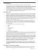
Figure 1 Integrity Virtual Server Manager with HP SMH • HP Matrix Operating Environment for HP-UX Integrity Virtual Server Manager is installed as part of Matrix Operating Environment for HP-UX that runs under HP Systems Insight Manager on a server reserved for use as a central management server (CMS). The CMS can run on HP-UX or Windows platforms. HP Systems Insight Manager serves as the central point of administration for complete resource-lifecycle management for multi-OS environments.
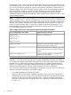
Figure 2 Integrity Virtual Server Manager with HP Systems Insight Manager and the HP Matrix Operating Environment for HP-UX In this environment, you can use Integrity Virtual Server Manager in seamless integration with other Matrix Operating Environment for HP-UX components. These interlinking components enhance the functionality and flexibility of your virtual server environment.
HP-UX. It simplifies the deployment of automated workload management policies across multiple servers, and provides centralized monitoring and reporting and improved server utilization to assist in meeting your service level objectives. Using Integrity Virtual Server Manager with Matrix Operating Environment for HP-UX, you can create, view, and modify gWLM policies for VMs or vPars.
2 Installing Integrity Virtual Server Manager This chapter discusses how to install Integrity Virtual Server Manager on your system or on the systems you will manage, including setup and software requirements, licensing requirements, and how to set WBEM security credentials. System and software requirements System requirements for the VSP, VMs, and vPars are described in the HP-UX vPars and Integrity VM Administrator Guide manual.
• The VM Provider provides VSP and guest configuration data. This information is delivered using WBEM. To use Integrity Virtual Server Manager to view configuration data, install the VM Provider (VMProvider bundle) that is provided with Integrity VM. Install the VM Provider on the VSP and on each VM or vPar when you install the HP Integrity VM product. If you upgrade Integrity VM, be sure to keep the VM Provider up to date, too.
#/usr/sbin/swlist VMMGR NOTE: Beginning with the HP-UX 11i v3 March 2009 Operating Environment Update Release (OEUR), you can optionally install Integrity Virtual Server Manager on HP SMH as part of the VSE-OE or DC-OE. Licensing requirements The licensing requirements for Integrity Virtual Server Manager on HP SMH include the following: On HP SMH, Integrity Virtual Server Manager is installed separately on a VSP. You must have a license for Integrity VM and have Integrity VM installed on that VSP.
Setting WBEM credentials in HP Systems Insight Manager Any VMs or vPars that are not managed nodes do not have any credentials available, and Integrity Virtual Server Manager cannot contact them. These machines are displayed, but some of the information that can be gathered from the managed nodes is not displayed for non-managed nodes. You can set credentials in HP Systems Insight Manager for a global configuration across multiple systems by selecting Options→Protocol Settings→Global Protocol Settings...
individual systems, Integrity Virtual Server Manager does not collect utilization data and operating system information for the excluded systems. You can also save the user name and password entries in obscured format in the file system. This allows you to use the same setting each time you enter Integrity Virtual Server Manager through HP SMH. To save these entries, select the Save user name and password settings in the file system check box, and then click OK.
When a utilization meter is dimmed, a label next to the meter indicates the probable cause. These labels and status indicators are described in “Utilization meter status/error information” (page 131). Virtual LAN interface I/O utilization on the VM or vPar Properties Network tab: For a VM or vPar with invalid credentials, either the No Perm. or No Data label appears next to the meter.
1. Locate the WBEM services provider certificate file (cert.pem) on the VM or vPar to which you want to connect. To find the correct file, open the WBEM services Provider configuration file, which can be found in the following locations: • For Windows: %PEGASUS_HOME%\cimserver_current.conf • For HP-UX: $PEGASUS_HOME/cimserver_current.conf (The default value for PEGASUS_HOME on HP-UX is /var/opt/wbem.) The location of the server certificate file is configured by the sslCertificateFilePath setting.
3 Accessing and Navigating Integrity Virtual Server Manager You access Integrity Virtual Server Manager through a web browser. This chapter explains how to access Integrity Virtual Server Manager from HP SMH and HP SIM. This chapter also explains how to access Integrity Virtual Server Manager help. Information about possible access failures and the messages that might be seen is included in Appendix A (page 129).
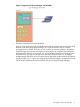
Figure 5 HP Matrix OE visualization — Visualization tab 2. The first time you start HP Matrix OE visualization, the Visualization tab appears with the default Physical and Virtual perspective, which shows all physical and virtual nodes in graphical compartments. When you start HP Matrix OE visualization any time after, the software checks whether you had previously set a default view by modifying user preferences (modify user preferences by selecting Configure→User Preferences...
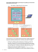
3. On the HP Matrix OE visualization Visualization tab, select the VSP or VM (vPar) that you want to manage. For example, in the Integrity VM representation shown in Figure 7 (a closeup from the screen shown in Figure 6 (page 22)), you can select VSP system chili3 by clicking the monitor icon beneath the VSP name. (If you hover your cursor over the icon, a pop-up pane displays explanatory text.) Selecting a VSP monitor icon displays the Integrity Virtual Server Manager VSP Virtual Servers tab.
NOTE: When you access Integrity Virtual Server Manager for the first time from HP SMH, you might encounter an End User License Agreement (EULA). You must accept this agreement to continue using the Integrity Virtual Server Manager product. Figure 8 HP SMH: accessing Integrity Virtual Server Manager If you have already saved WBEM credentials for each VM or vPar, selecting Integrity Virtual Server Manager displays the VSP Virtual Servers tab.
NOTE: The Integrity Virtual Server Manager navigation aids available in a particular view vary according to the view. The view in Figure 9 shows most of the navigation aids that Integrity Virtual Server Manager provides. Missing from this view are navigation buttons such as Previous and Next, visible in some of the Create Virtual Machines or Virtual Partitions wizard pages (discussed in “Creating VMs” (page 81) or “Creating vPars” (page 109)).
The icon in the OS column indicates that the VM is in a suspended state. In this particular view (the VSP Virtual Servers tab), if a VM is migrating, an icon indicates the direction of 7 migration. In the last row of the table, the icon indicates the VM is migrating to another VSP. For more information about migration status icons, see “VSP Virtual Servers tab” (page 31). The meanings of these and other status icons are summarized in “Status indicators” (page 131).
4 Using Integrity Virtual Server Manager views and tabs Integrity Virtual Server Manager provides three basic views, each with several tabs, as described in the following sections. You can print any of the VSP or vPar or VM tabs by clicking View Printer-friendly beneath the Integrity Virtual Server Manager menu bar, on the left side of the page. This redisplays the tab in a format suitable for printing. To print the tab, click Print. To switch back, click View Normal.
Figure 10 VSP view General tab 1 2 3 4 5 6 7 8 The “VSP General tab” (page 28) displays information about the VSP system. The “VSP Virtual Servers tab” (page 31) displays information about the state of VMs or vPars in the VSP system. The “VSP Virtual Switches tab” (page 33) shows information about the virtual switches on the VSP. The “VSP Network tab” (page 34) shows all mappings from virtual network interface cards in the VMs or vPars to the physical network interface cards in the VSP system.
Quick reference Figure 11 VSP General tab 1 2 3 4 Displays this window in a format suitable for printing. Describes resources in the VSP system. Describes the status of VMs or vPars in the VSP system and identifies external managers. If the VSP VMs or vPars are being managed by gWLM or HP Serviceguide, the External Managers field displays gWLM or Serviceguide. If the vPars are managed by gWLM, the field provides a hyperlink that enables you to access gWLM.
Screen details VSP Information • VSP name: The hostname of the VSP system (as well as the nPartition name and link to Partition Manager for this nPartition, if the VSP system is contained within an nPartition). • Resource inventory. ◦ Physical CPU Core Count: The number of processors. ◦ Physical CPU Core Speed: The speed of processors. ◦ Physical Memory: The amount of memory. ◦ Online Migration: Indicates whether the VSP is enabled and licensed to support online migration of VMs.
• VSP CPU Utilization: An aggregate showing how busy the VSP is with respect to the processes and VMs or vPars that are executing on it. • Physical Memory currently in use: A started VM or vPar requires the total amount of memory defined for that VM or vPar. If the memory is set to be reserved, the stopped vPar also requires the total amount of memory defined for it.
In Integrity Virtual Server Manager on Matrix Operating Environment, you can click a meter to view a snapshot of Capacity Advisor historical data. Virtual Server Manager is on SMH and does not provide an option to generate a Capacity Advisor report. Figure 13 shows an example of the full-width view of the VM or vPar information table displayed by the VSP Virtual Servers tab. (To see the entire table, you might have to scroll horizontally or maximize your window.
NOTE: Although only one VM migrates at a time, you might see indication of two machines migrating simultaneously to another VSP. The first migration has actually completed but Integrity Virtual Server Manager has not yet received notification from the VM Provider. For more information on the meanings of status icons, see “Status indicators” (page 131) • Operating System: Displays the operating system type and version information for the VM or vPar.
1 2 3 4 Displays this window in a format suitable for printing. Allows you to perform an action on the virtual switches. Select the box for a vswitch, then select a command from the menu to perform an action on the vswitch. To perform an action on all the virtual switches, select the box in the header row. Displays information about the virtual switch by taking you to the Vswitch Properties General tab. Indicates whether the physical backing device supports Accelerated Virtual Input/Output (AVIO).
Quick reference Figure 15 VSP Network tab 1 2 3 4 5 6 Displays this window in a format suitable for printing. Displays detailed information about the VM or vPar by taking you to the VM or vPar Properties General tab. Allows you to perform an action on the VM or vPar or I/O device. Select the box, then select an action from one of the menus available on the Integrity Virtual Server Manager menu bar.
Table 3 Network device icons Icon Description Physical or virtual network card Virtual switch Virtual LAN (VLAN) A question mark within the device icon, such as , indicates that the type of device cannot be determined. The device type cannot be determined, for example, when the device has been removed from the VSP but not from the VM or vPar. Screen details Network tab column layout Figure 16 depicts the column layout for the VSP Network tab.
Figure 17 Virtual Network Interfaces column Referring to Figure 17, note the following: • The icons next to the name of the VM or vPar and next to the network interface devices show the status of the system or interface. A question mark (?) means no information is available. • Clicking the name of the VM or vPar (for example, vpar001) displays general information about the VM or vPar.
Figure 18 Virtual Switches column Referring to Figure 18, note the following: • The icon next to the name of the virtual switch shows whether the virtual switch is operational. • Clicking the box near the virtual switch name allows you to perform operations on the virtual switch by using one of the menus available from the Integrity Virtual Server Manager menu bar. • Clicking the virtual switch name displays general information about the virtual switch.
Figure 19 Virtual LAN If a virtual switch has VLANs configured on it, each VLAN appears as a separate box within the virtual switch box. The virtual NICs from the VMs or vPars are connected to the appropriate VLAN box by a color-coded line. The switch port used by the virtual NIC is listed in its box. The VLAN boxes list the switch ports that are using that VLAN ID. For ports on the switch that are not associated with a VLAN, the virtual switch contains a box labeled No VLAN.
Physical Network Interfaces column contents Each box in the Physical Network Interfaces column represents one of the following: • A physical network interface card in the VSP Figure 20 Physical network interface card • An APA. When multiple physical network interface devices are aggregated using the Auto Port Aggregation (APA) software package, they are displayed as network devices inside an APA box.
Colors The connections are color coded to help you identify interconnected elements. NOTE: The actual colors shown do not imply any specific meaning. The colors are provided to help you understand the connections from virtual to physical devices. Focus links Clicking one of these links simplifies the display by showing only the item that was selected and the elements that are directly attached to it.
Status icons These indicate whether an item is operational. Position the cursor over the icon to view a textual description. For more information about status icons, see “Status indicators” (page 131). VSP Storage tab The VSP Storage tab shows the mappings from the virtual storage devices in the VMs or vPars to the physical storage devices in the VSP system. Quick reference Figure 22 VSP Storage tab 1 2 Displays this window in a format suitable for printing.
you navigate back (you continue to see the complex view on return). If the box is unchecked, it remains unchecked when you return (you continue to see the simple view). The check box state on the VSP Storage tab does not affect the state of the same check box on the VM or vPar Properties Storage tab. For example, selecting the check box on the VSP Storage tab does not automatically affect the check box and view of the VM or vPar Properties Storage tab.
Table 4 Network device icons (continued) Icon Description Burner Changer File Directory (folder) Storage adapter A question mark within the device icon, such as , indicates that the type of device cannot be determined. The device type cannot be determined, for example, when the device has been removed from the VSP but not from the VM or vPar. Virtual device type: • The virtual device type and subset of the hardware path are shown with each virtual device.
Screen details Storage tab column layout Figure 23 depicts the column layout for the VSP Storage tab. Figure 23 Storage tab column layout The VSP Storage tab consists of three columns with the following titles. The contents of each column are described in the subsections that follow. Virtual Storage column contents As shown in Figure 24, this column displays the virtual storage devices in the VMs or vPars. The virtual storage devices are grouped by VM or vPar.
vPar or device, you can return to see all the VMs or vPars or devices by using the Show All link visible on the focus page. Logical Storage column contents This column displays information about logical storage devices, including the files and logical volumes that reside on physical storage devices. Each box represents a logical storage device, as in Figure 25.
Figure 27 Physical storage detail from HP Integrity VM Version 4.0 or later VSP The following items describe physical storage details in Figure 27: • The box on the top is the storage device representation with the persistent device special file (agile addressing). The first line describes the storage device (HP 300 GST3300007LC). The next line below that (/dev/rdsk/disk3) displays the persistent device special file (DSF) path for the storage device.
Colors The connections are color coded to help identify interconnected elements. NOTE: The actual colors shown do not imply any specific meaning. The colors are provided to help you understand the connections from virtual to physical devices.
Bar graphs The bar graphs are utilization meters that indicate the current I/O throughput of a device or interface card. When running the Integrity Integrity Virtual Server Manager with Matrix Operating Environment, some bar graphs are selectable and display a view of the historical data related to the graph. Status icons These indicate whether an item is operational. You can hover the cursor over the icon to view a textual description.
Quick reference Figure 29 GUID Resources tab 1 2 3 4 5 6 Select Hidden node WWN ranges to hide the node WWN values and to display the port WWN values only. If you delete a port WWN range, the corresponding node range is also deleted. Select a WWN range to modify or delete. The name of the node or port WWN range. Select a port WWN range and click Modify. This allows you to modify the WWN ranges.
Modifying WWN ranges The Modify option in the GUID Resources tab allows you to modify the unique WWN range for the node or port. To modify the unique WWN range for a port: 1. Select the port WWN range that you want to modify from the WWN ranges table and click Modify. The Start Address and End Address fields are displayed, as shown in Figure 31. Figure 31 Modify WWN ranges 2. 3. Update the Start Address and End Address fields to specify the new WWN range.
Figure 33 DIO Pool tab 1 2 3 The SHOW DIO Table Option lists the options to view the DIOs in the host or HPVM. When you select an option, its corresponding table is displayed. The following options are listed: • Show All DIO Resources displays both the host DIO tables and the HPVM DIO table. • Show Host DIO Resources displays only the host DIO table. There are two host DIO tables, one with IP and Vswitch and the other without IP and Vswitch. • Show HPVM DIO Resources displays only the HPVM DIO table.
The default setting is, the Change Restricted Status and Change Owner buttons are disabled. To enable them, you must select one or more DIOs. Figure 34 (page 53) shows the Host DIO table . Figure 34 Show HOST DIO Resources You must select a DIO check box in the host DIO table to enable Change Restricted Status and Change Owner. Click Change Restricted Status to change the restricted status of the DIO owned by host. For more information, see “Changing the restricted status of host DIOs” (page 57).
Figure 35 DIO Pool tab — HPVM DIO table You must the DIO check box in the HPVM DIO table to enable Change Label and Change Owner. Click Change Label to change the label of the DIO. For more information, see “Changing the labels of HPVM DIOs” (page 59). Click Change Owner to change the owner of the DIO to host. For more information, see “Changing the owner of HPVM DIOs to host” (page 59).
Table 5 Show host DIO resources (continued) Name Description Assignment Level Indicates whether the operation of the DIO is at a function level or device level. In Function Level Assignment (FLA), each function is shared among several VMs or vPars. In Device Level Assignment (DLA), an entire device is assigned to the same guest OS. In the DIO pool, all functions of DIOs with device-level assignment are placed together.
Table 6 Show HPVM DIO resources (continued) Name Description Description Displays a description of the DIO network adaptor. For example, the name of the adaptor is provided, AM225-60001 HP Integrity PCIe 2-port 10GbE-SR Fabric Adapter. Label Indicates the label of the DIO. HPVM DIOs of a DLA group have the same label. Used by Guest Indicates the VMs or vPars that are configured to use this DIO. Changing the owner of host DIOs to HPVM You can change the owner of a DIO from host to HPVM.
Figure 37 Change owner of host DIOs to HPVM – Assign new labels check box not selected To change the owner of DIOs: 1. 2. 3. Select Show HOST DIO Resources in the DIO Pool tab. The host DIO table appears. Select the check boxes of preferred DIOs. This enables the Change Owner button. Click Change Owner button to open the Change owner of the selected DIOs to HPVM page. NOTE: If the status of the DIO is restricted, you cannot change the ownership of the DIO.
Figure 38 Change restricted status of a DIO Figure 39 Change unrestricted status of a DIO page To change the restricted status: 1. 2. 3. Select Show HOST DIO Resources in the DIO Pool tab. The host DIO table appears. Select the check boxes of preferred DIOs to change the restricted status. This enables the Change Restricted Status button. Click Change Restricted Status button to open the Set restricted status for the selected host DIOs page. Restricted and Unrestricted options are displayed.
Changing the owner of HPVM DIOs to host You can change the owner of DIOs from HPVM to host. Figure 40 Change owner of HPVM DIOs to host To change the owner of DIOs: 1. 2. 3. 4. Select Show HPVM DIO Resources in the DIO Pool tab. The HPVM DIO table appears. Select the check boxes of preferred DIOs to change the owner. This enables the Change Owner button. Click Change Owner to open the Change owner of the selected DIOs to HOST page.
Figure 42 Delete label of HPVM DIO To set or delete the label of DIOs: 1. 2. 3. Select Show HPVM DIO Resources. The HPVM table appears. Select the check boxes of preferred DIOs to change the labels. This enables the Change Label button. Click Change Label to open the Change labels for the selected DIOs page. This page displays the following options: Depending on the option you select, the page displays the data. 4. Select one of the two options.
Figure 43 VM or vPar Properties View: General tab 1 2 3 The “VM or vPar properties general tab” (page 61)displays information about the general state of the VM or vPar. The “VM or vPar Properties Network tab” (page 66) displays information about the network devices for the VM or vPar. The “VM or vPar Properties Storage tab” (page 68) displays information about the storage devices for the VM or vPar.
Quick reference Figure 44 VM or vPar Properties General tab 1 2 62 Displays this window in a format suitable for printing. Lists VM or vPar identification, status, and general configuration details. To update status information, click Refresh Data.
running on the VSP, the Graceful Stop Timeout is displayed, as in this screen example. The timeout value is set by using the hpvmmodify command at the VSP command line. This section of the screen includes configuration and status information about online migration.
(On) and the name of the VSP currently managing the VM or vPar (Serviceguard guest package). • Operating System: Indicates the last OS type to be booted on this VM or vPar. If the VM or vPar has never been booted, this field contains the value that was supplied when the VM or vPar was created.
Figure 45 Online migration phases Each of the following fields display the phase's percentage of completion: • Init Phase: The initialization phase when the source and target VSPs establish connections, perform various checks, starts the target guest, and so forth. • Copy Phase: Tracks writes to guest memory and copies all of guest memory from the source to the target VSP. • I/O Quiesce Phase: Completes outstanding I/O and queues new I/O requests for the target guest.
• Minimum Memory Size: The lowest value to which the VM or vPar can attempt to decrease its memory while the OS is running. • Maximum Memory Size: The highest value to which the VM or vPar can attempt to increase its memory while the OS is running. • VM or vPar is Allowed to Control Memory Size: Indicates whether the Allow dynamic control of memory size from the VM or vPar is in effect.
Quick reference Figure 47 VM or vPar Properties Network tab 1 2 3 4 5 6 7 Goes back to the previous view, in this case the Integrity Virtual Server Manager VSP view. When you access the Virtual Server Manager Properties view from another Integrity Virtual Server Manager view (such as the VSP view), the link returns you to that previous view. If you had accessed the Virtual Server Manager Properties view directly from Matrix OE visualization, the link returns you to Matrix OE visualization.
VM or vPar Properties Storage tab The VM or vPar Properties Storage tab works similarly to the VSP Storage tab. The difference between the two tabs is that the VM or vPar Properties Storage tab shows only the devices related to a single VM or vPar, whereas the VSP Storage tab shows all the devices (for the VSP and all VMs or vPars) in the Integrity Virtual Server Manager environment.
4 5 6 The utilization meter (bar graph) displays I/O throughput data, if available. The data is a 5-minute average that is calculated and updated on 5-minute boundaries. If the data cannot be displayed, the meter is dimmed (as in the meter below this one) and a label indicates the probable cause. For a description of meter labels, see the Error messages and troubleshooting topic.
Figure 49 Vswitch Properties view: General view 1 2 The “Vswitch Properties General tab” (page 70) displays information about the general state of the virtual switch. The “Vswitch Properties Network tab” (page 71) displays network details about the virtual switch. Vswitch Properties General tab The Vswitch Properties General tab shows the status, configuration properties, and port assignments of a virtual switch.
1 2 3 Goes back to the previous view, in this case the Integrity Virtual Server Manager VSP view. When you access the Vswitch Properties view from another Integrity Virtual Server Manager view (such as the VSP view), the link returns you to that previous Integrity Virtual Server Manager view. Displays this window in a format suitable for printing. Displays virtual switch configuration information.
Quick reference Figure 51 Vswitch Properties Network tab 1 2 3 4 5 6 Goes back to the previous view, in this case the VM Properties view. When you access the Vswitch Properties view from another Integrity Virtual Server Manager view (such as the VM Properties view), the link returns you to that previous Integrity Virtual Server Manager view. Displays this window in a format suitable for printing. Displays information about the VM or vPar by taking you to the VM or vPar Properties General tab.
5 Using Integrity Virtual Server Manager menus Integrity Virtual Server Manager views provide a menu bar beneath the tabs row, as shown in Figure 52. The menus enable you to perform a variety of actions. Not all actions (menu options) are available from every screen view. Actions are enabled or disabled based on the state of the system, the view you are in, and the objects in that view that are currently selected. Actions that are disabled are dimmed and unselectable.
Figure 53 Integrity Virtual Server Manager Tools menu Table 9 describes the Tools menu options and where to obtain more information in this manual. More detailed information is provided by the Integrity Virtual Server Manager help. Table 9 Integrity Virtual Server Manager Tools menu options Menu Selection Action Summary More Information Tools→Start VM... This menu is enabled only for VMs. “Starting VMs” (page 88). nl Tools→Stop Virtual Machine... This menu is enabled only for VMs.
Table 9 Integrity Virtual Server Manager Tools menu options (continued) Menu Selection Action Summary More Information Tools→Reset Virtual Partition... Restarts an already started vPar, “Resetting vPars” (page 113) taking it first to an Off state (powered off) and then to an On state (powered on). Starts a stopped vPar. Tools→Start Virtual Switch...
Table 10 Integrity Virtual Server Manager Create menu options Menu Selection Action Summary More Information Create→Virtual Machine... This menu is enabled only for VMs. “Creating VMs” (page 81) Starts the Create Virtual Machine wizard, which guides you through the procedure of creating a VM. Each step presents a dialog that asks you to specify required information. Create→Virtual Partition...
Integrity Virtual Server Manager help and the HP-UX vPars and Integrity VM Administrator Guide manual. Table 11 Integrity Virtual Server Manager Modify menu options Menu Selection Action Summary Modify→CPU Count... Modifies the number of virtual CPUs allotted to a VM or a vPar that has been configured for symmetric multiprocessing. The changed value takes effect when the VM or vPar is restarted. Modify→Memory... Modifies the amount of virtual memory (entitlement) to allocate to the VM or vPar.
Figure 56 Integrity Virtual Server Manager Delete menu Table 12 describes the Delete menu options and where to obtain more information in this manual. More detailed information is provided by the Integrity Virtual Server Manager help. Table 12 Integrity Virtual Server Manager Delete menu options Menu Selection Action Summary More Information Delete→Virtual Machine..... This menu is enabled only for VMs. “Deleting VMs” (page 92) Delete→Virtual Partition...
NOTE: The Capacity Advisor Data item is displayed only when you use Integrity Virtual Server Manager with Matrix Operating Environment for HP-UX; it is not displayed when using Integrity Virtual Server Manager through HP SMH. The accessibility of the other menu items depends on the current view and selections. For example, to access the VM or vPar log from the VSP Virtual Servers tab, a VM or vPar must be selected, as shown in Figure 57.
6 Working with VMs or vPars This chapter describes tasks you can perform to create and manage VMs or vPars and their resources. NOTE: Integrity Virtual Server Manager version 6.1 supports only one type of guest. If the first guest created on Virtual Server Manager is a vPar, then only vPar guests can be created on that VSP. If the first guest created is a VM, then only VMs can be created on that VSP.
HP-UX as the intended guest OS, with Integrity VM 3.0 or later installed on the VSP), the memory screen allows you to set dynamic memory parameters. NOTE: An up-to-date version of the WBEM Utilization Provider (UP) must be installed on the VM or vPar to enable HP Capacity Advisor and the memory utilization meters in Integrity Virtual Server Manager and Integrity VM to reflect the dynamic change in memory.
1. 2. 3. 4. Select the preferred DIOs from the HPVM DIO table. These DIOs do not have an IP address and are not associated with a Vswitch. If you want to enter the Bus, Device, and MAC parameters for the selected DIOs, select Specify virtual address parameters (advanced). If you do not want to enter the parameters, leave the check box blank. Click Add to List to add the selected DIOs to the VM. The Specify DIOs page appears, where the selected DIOs are listed.
If the VSP is running HP-UX 11i v3, the Add Storage Device screen gives you the choice of listing storage devices by their agile address (the default) or by their legacy address. HP recommends using agile device addressing when configuring storage devices. This provides benefits especially for multipath devices. With legacy addressing, the screen lists one entry for each path to a storage device that has multiple paths.
NOTE: If you use Integrity Virtual Server Manager to manage a VSP running Integrity VM Version 3.5 or earlier, Integrity Virtual Server Manager does not fully support virtual device special files located in /hpap (introduced in HP StorageWorks Secure Path software Version 3.0F SP2) as backing devices for virtual storage.
on the VSP and the VM. If the intended OS on the VM does not support AVIO, you are warned of this. In addition, HP strongly recommends that AVIO components (such as drivers and libraries) on the VM and VSP be updated to the latest release of the OS. If the VM OS is Windows or Linux, install additional AVIO-compatible drivers on the VM; the Windows and Linux AVIO drivers include instructions for installing the drivers on VMs.
NOTE: If the VM is being managed by gWLM, you cannot modify the vCPU entitlement. When you access the Virtual Machine vCPU Entitlement page, the following error message is displayed, where virtual-machine-name is the name of the VM: The processor entitlement for VM virtual-machine-name cannot be modified because it is being managed by gWLM. To adjust the processor entitlement for this VM, use gWLM to change the policy associated with this VM.
NOTE: The list of possible backing devices for the storage device you want to add can include file and directory backing devices that have not been associated with a particular VM or vPar, or that were associated with VMs or vPars that have been removed or from which the associated virtual devices have been removed. You can create a file as a backing storage device for a virtual disk. You can add DVD burners, tape devices, and changers if they are emulated SCSI adapters; they are added as attached devices.
1. 2. From the VSP General tab, select the VSP Virtual Servers tab (or any tab that allows you to select one or more VMs). Select one or more VMs to start by clicking the appropriate check boxes. Alternatively, you can access the VM Properties view, in which case no selection is necessary; the VM being viewed is implicitly selected. 3. Select Tools→Start Virtual Machine... from the Integrity Virtual Server Manager menu bar. A page similar to that shown in Figure 58 is displayed.
NOTE: If the OS is running on a VM that you want stopped, HP recommends that you shut down the OS before stopping the VM. This ensures that all applications are shut down cleanly. You cannot stop a VM that is currently migrating online. You must wait until migration completes. If the selected VM has migrated to another VSP (the target), the VM (on the source VSP) is in the Not Runnable state: attempts to stop the VM will fail. 1. 2.
Restarting VMs When you choose to restart one or more VMs, Integrity Virtual Server Manager stops a VM that is already started, and then restarts it; if a machine is stopped, Integrity Virtual Server Manager starts it. Once a VM starts, the resources assigned to the VM are allocated for its use. The Restart and Start functions are similar except the Restart function first stops a VM that is already started, while the Start function does not (it leaves the started VM as is).
5. The Command Preview area shows the commands that Integrity VM will perform to restart the VMs. Click OK to perform the action. For information about possible reasons that a VM might not start, see “Troubleshooting VM or vPar problems” (page 132). Deleting VMs To delete a VM, select Delete→Virtual Machine... from the Integrity Virtual Server Manager menu bar. The Virtual Machine...
Some of the most common reasons for migrating VMs online include the need to: • Vacate the source VSP system for maintenance purposes without disrupting services • Perform a rolling upgrade of a VSP, moving its running guests to another VSP, upgrading the VSP, then moving the guests back • Populate a new VSP with one or more VMs already configured and tested on the source • Move VMs to take advantage of a particular resource or feature on the target VSP, without losing application availability • Ba
quickly. Configuration requirements for online migration are more elaborate than for offline migration. Some of the basic migration requirements include the following; for complete details, see the HP-UX vPars and Integrity VM Administrator Guide manual: • For online migration, the source and target VSPs must be running HP Integrity VM Version 4.1 or later.
Migration status and error notification The migration status of a VM — including the direction of migration, percentage completion per phase (for online migration only), and error messages — is displayed on the VM Properties General tab. The VSP Virtual Servers tab also indicates migration status (use this tab to monitor the migration of multiple VMs). For more information, see “VM or vPar properties general tab” (page 61) and “VSP Virtual Servers tab” (page 31).
Figure 61 Migrate Virtual Machine: Step 1 of 2 3. 4. 5. Specify the target VSP name, alias, or IP address. The target must be a valid VSP and must be accessible by the source VSP. If you intend to migrate a VM online, this VSP must be licensed and enabled for online migration. If you want the VM configuration removed from your source VSP after the migration completes, select the check box provided for that purpose. Make this selection if you never intend to migrate the VM back to this VSP.
Figure 62 Migrate Virtual Machine: Step 2 of 2 6. Inspect the commands. If they suit your needs and you want to go ahead with the migration, click Finish. If you want to tailor the commands to be used for migrating the selected VMs, you can enter the desired commands manually on the VSP.
Figure 63 Virtual Machine Suspend 3. The Command Preview area shows the commands that Integrity VM performs to suspend the VM. Click OK. The VM is suspended and the Virtual Servers tab is displayed. You can view the status as Sp in the OS column against the selected VM, as shown in Figure 64. Figure 64 Suspend status Resuming VMs A VM can be resumed only if it is in a suspended (SP) state. Resuming a VM saves time as it does not involve the actual shutdown and reboot of the OS.
1. 2. Select a VM in a suspended state. Select Tools→Resume Virtual Machine. The Resume Virtual Machine screen is displayed, as shown in Figure 65. Figure 65 Virtual Machine Resume page 3. The Command Preview area shows the commands that Integrity VM performs to resume the VM. Click OK. The VM is resumed and the Virtual Servers tab is displayed. The status turns On in the OS column against the selected VM.
1. Select Tools VM Move Suspend. The screen to specify the new directory is displayed, as shown in Figure 66 Figure 66 Virtual Machine move suspend 2. To change the default directly, select the Specified directory option and click Browse. The screen listing all the directories is displayed, as shown in Figure 67. Figure 67 Virtual machine browse directory 3. 4. Select a directory and click Select. The screen goes back to the VM Move Suspend page.
To create a vswitch, select Create→Virtual Switch from the Integrity Virtual Server Manager menu. This displays a page similar to that shown in Figure 68. Figure 68 Create Virtual Switch page The table on the screen shown in Figure 68 displays the following information: • LAN interface: Shows the physical LAN interface to which a vswitch can be attached. The “(none)” entry indicates that the vswitch is local, meaning that it not connected to a LAN interface.
With HP Integrity VM, AVIO requires a vswitch that has a physical network device as the backing device (local vswitches such as localnet are not supported). In addition, the physical NIC that backs the virtual switch must have an AVIO-compatible driver. For more information about AVIO requirements, see the HP Integrity Virtual Machines documentation available at http://www.hp.com/go/hpux-hpvm-docs. Create the virtual switch by performing the following steps: 1. 2. (Required) Enter a virtual switch name.
lists each command and whether the command succeeded, failed, or was not attempted. Clicking OK on the error page returns you to the Create Vswitch page. Starting, stopping, and deleting virtual switches To start or stop a virtual switch, select Tools→Start Virtual Switch... or Tools→Stop Virtual Switch... from the Integrity Virtual Server Manager menu bar. To delete a virtual switch, select Delete→Virtual Switch....
NOTE: You cannot remove a device that is currently being used by the guest OS or if I/O is outstanding. If a VM or vPar is running the Windows operating system, Integrity Virtual Server Manager indicates that it will not remove the VM or vPar's devices. The operating system must be shut down first. If a VM or vPar is running HP-UX, devices selected for removal might not be removed until you restart the VM or vPar.
3. Select Tools→Open iLO Console or Open Virtual iLO Remote Console from the Virtual Servers menu bar. The iLO Console screen is displayed. Figure 69 iLO console The Main menu is listed: • CO: Console • CM: Command Menu • CL: Console Log • SL: Show Event Log • VM: VM Menu • HE: Main Help Menu • X: Exit Connection Opening virtual iLO remote console The remote console is a terminal to manage a VM or vPar. This feature allows you to access the guest directly.
Deleting virtual iLO remote console The Delete option in the Console tab allows you to delete the current IP address and Netmask of the virtual iLO remote console for the selected VM or vPar. To delete the virtual iLO remote console settings of a VM or a vPar: 1. Click Delete against the VM or vPar for which you want to delete the virtual iLO remote console details. The Delete virtual iLO remote console screen is displayed. Figure 70 Delete virtual iLO remote console 2.
Adding DIOs You can add DIOs to a VM or vPar. Figure 72 Add DIOs to VM or vPar page To add DIOs: 1. 2. Select a guest from the Virtual Servers tab. Click Modify→ Add DIO. The Add DIOs to (VM or vPar) page is displayed. The Add DIO menu is enabled only after you select a guest. If more than one guest is selected, the menu items are not enabled. 3. Select DIOs from the HPVM DIO table.
Figure 73 Replace DIO H/W path page To replace the DIO h/w path: 1. 2. Select a guest from the Virtual Servers tab. Select Modify→Replace DIO H/W Path.... After you select a guest, the Replace DIO H/W Path... menu is enabled. If you select more than one guest, the menu items are not enabled. The Modify DIO H/W Path... page is displayed. Two tables are displayed, one is the guest DIO table and the other is the HPVM DIO table. 3. 4.
2. Click Modify→Replace DIO MAC Address.... The Modify DIO MAC address page is displayed. The Replace DIO MAC Address... menu is enabled only after you select a guest. If you select more than one guest, the menu items are not enabled. 3. 4. Select DIOs in the guest DIO table. Click Modify MAC Address & Command Preview, and then enter the new MAC address in the new table that is displayed. NOTE: To view errors if any, related to the data that is entered, click Modify MAC Address & Command Preview. 5.
To add DIOs: 1. Click Add DIO.... The Add a DIO to vPar... screen is displayed. 2. Select the preferred DIOs from the HPVM DIO table. These DIOs do not have an IP address and are not associated with a Vswitch. 3. If you want to enter the Bus, Device, and MAC parameters for the selected DIOs, select Specify virtual address parameters (advanced). If you want to use the default parameters, leave the check box blank. 4. Click Add to List to add the selected DIOs to the vPar.
devices on HP-UX 11i v2 and HP-UX 11i v3 vPars. The attached devices configured using AVIO (avio_stor adapter), have the following benefits over attached devices configured with VIO (scsi adapter): 1. Allow sharing of tapes, changers, and burners among multiple vPars and VSPs 2. Support of USB 2.0 DVD burners 3.
• Add DIO to add DIOs to a VM or vPar. For more information, see “Adding DIOs” (page 107). • Replace DIO H/W path to replace the h/w path of a DIO owned by a guest, VM or vPar. For more information, see “Replacing DIO H/W path” (page 107). • Replace DIO MAC address to replace the MAC address of DIOs owned by a guest, VM or vPar. For more information, see “Replacing DIO MAC address” (page 108). • WBEM Credentials to set or change WBEM credentials for vPars.
Stopping vPars To stop one or more vPars: 1. Click the Virtual Servers tab. The vPars are listed in this tab. 2. 3. Select one or more vPars by selecting the check box against the vPar. Select Tools→Stop Virtual Partition from the vPars menu bar. The Stop Virtual Partition screen is displayed. Figure 76 Stop Virtual Partition The General Preview area shows the vPars that are going to be stopped. The Real Command area displays the commands that the vPar Manager will execute to stop the vPars. 4.
function resets all the vPars. However, if you do not want the already booted partitions rebooted, in other words, you just want the stopped partitions booted, use the Boot function instead. To reset one or more vPars: 1. Click the Virtual Servers tab. The vPars are listed in this tab. 2. 3. Select one or more vPars by selecting the check box against each required vPar. Select Tools→Reset Virtual Partition from the vPars menu bar. The Reset Virtual Partition screen is displayed.
Deleting vPars Deleting a vPar removes all configuration files for the vPar and frees up any resources assigned to it, thereby the available resources can be assigned to other vPars. Deleting a vPar does not delete files and data residing on the virtual storage or backing storage that is assigned to the vPar. NOTE: Before you remove a vPar, you must stop the vPar or put to Off state (powered off). By default, vswitch VLAN port assignments are removed when the vPar is deleted.
Replacing DIO MAC address For details about replacing DIO MAC addresses, see “Replacing DIO MAC address” (page 108). Deleting DIOs For details about deleting DIOs, see “Deleting DIOs” (page 106).
7 Collecting and viewing utilization data Certain Integrity Virtual Server Manager views include utilization meters (bar graphs) that display current utilization data for a resource. For example, the VSP Virtual Servers tab includes several utilization meters for each vPar and VM listed, as shown in Figure 79. Using Integrity Virtual Server Manager with Matrix Operating Environment for HP-UX, you can click a meter to view a more detailed historical data report provided by HP Capacity Advisor.
Viewing utilization data Integrity Virtual Server Manager provides the following options for viewing utilization data. These assume the prerequisites discussed in “Enabling collection of utilization data” (page 117) have been met. • Utilization meters provided by Integrity Virtual Server Manager tabs. Table 16 lists the meters provided by Integrity Virtual Server Manager tabs. Utilization meters display current utilization data for the associated resource.
Table 16 Utilization meters available on Integrity Virtual Server Manager tabs (continued) Integrity Virtual Server Manager Tab Utilization Metrics CPU (%) Memory (%) Network I/O (throughput) Storage I/O (throughput) VM or vPar Properties Storage Vswitch Properties Network VSP (Physical Storage column) VM or vPar (Virtual Storage column) VSP (Physical Network Interfaces column) VM or vPar (Virtual Network Interfaces column) NOTE: Data reported by certain Integrity Virtual Server Manager CPU utilizat
Figure 80 View Capacity Advisor data screen: upper half 120 Collecting and viewing utilization data
Figure 81 View Capacity Advisor data screen: lower half The data collection view is provided by the Capacity Advisor Profile Viewer. The Profile Viewer displays historical utilization data along with additional information you provide. The Profile Viewer also enables you to examine different time intervals and different categories of data. In the Capacity Advisor graphs, you can view utilization data for both CPUs and memory.
Creating a historical utilization data report To use HP Capacity Advisor to create a historical utilization report that includes data for the target workloads, systems, complexes, or scenarios you specify, select the Tools→Capacity Advisor Historic Report menu item from the Integrity Virtual Server Manager menu bar. This menu item is available only when you use Integrity Virtual Server Manager with Matrix Operating Environment; it is not available when using Integrity Virtual Server Manager through HP SMH.
8 Viewing logs and version information Viewing VSP, VM, or vPar logs You can view the events logged by Integrity VM or vPar for the VSP by selecting View→VSP log... from the Integrity Virtual Server Manager menu bar. This gives a display similar to that created by the hpvmstatus -eM command (used at the Integrity VM CLI), except Integrity Virtual Server Manager limits the display to the most recent 1000 log lines.
1. Select View→VSP Log in the Virtual Servers tab. The log for VSP is displayed. Figure 82 View VSP log 2. Click OK to return to the previous screen. Viewing the VM or vPar log To view the VM or vPar log: 1. Select View→VM or vPar Log in the Virtual Servers tab. The log for VM or vPar is displayed. Figure 83 View vPar log 2. Click OK to return to the previous screen.
Virtual Server Manager menu bar. The resulting screen reports the current versions of Integrity VM, of Integrity Virtual Server Manager, and of the providers on both the VSP and each VM or vPar. Figure 84 shows an example of a screen. If “No Permission” is displayed where a VM's WBEM provider version or a vPar's WBEM provider version should be, the WBEM credentials (user name and password) have not been set for that vPar.
9 Support and other resources Contacting HP HP encourages your comments concerning this document. We are truly committed to providing documentation that meets your needs. Your comments and suggestions regarding product features will help us develop future versions of the Virtual Server Environment Management Software. Use the following email address to send feedback directly to the HP Matrix Operating Environment development team: vse@hpuxweb.fc.hp.com.
Typographic conventions This document uses the following typographic conventions. 128 Book Title Title of a book or other document. Linked Title Title that is a hyperlink to a book or other document. http://www.hp.com A website address that is a hyperlink to the site. Command Command name or qualified command phrase. user input Commands and other text that you type. computer output Text displayed by the computer. Enter The name of a keyboard key.
A Error messages, status indicators, and troubleshooting This appendix discusses error messages and troubleshooting related to Integrity Virtual Server Manager problems, and describes the status indicators that appear on some Integrity Virtual Server Manager screens and the error and status labels that might appear with utilization meters (bar graphs) displayed on certain Integrity Virtual Server Manager screens.
This command lists all the configuration parameters. Verify whether the enableNamespaceAuthorization parameter is set to TRUE. If it is set to TRUE, follow these steps: 1. To access WBEM Providers from HP Systems Insight Manager, run the following command: # cimauth -a -u -n root/cimv2/hpvm -R -W # cimconfig -s enableNamespaceAuthorization=true -p where, SIMUSER is the username created for SIM access. 2.
Status indicators In several actions and views, the status of a component is represented by an icon next to the component name or label. For example, the icon next to the name of a VM or a vPar shows whether the VM or vPar is up or down. A question mark (?) means no information is available. Table 17 explains the meaning of each status icon.
• No Comm. indicates that Integrity Virtual Server Manager is unable to communicate with the WBEM provider running on a VM or vPar. Hover the cursor over the meter to display an exception error message identifying the problem. A common reason for the No Comm. label to be displayed is a problem with trusted certificates.
are insufficient, missing or unavailable check box is selected on the Create Virtual Machines wizard Summary page, you can still have Integrity Virtual Server Manager create the VM. You will have to correct the conditions prior to starting the VM. • Failure starting a VM or a vPar The most likely cause for a VM or a vPar failing to start is missing, insufficient, or unavailable resources. Make sure the required resources are made available.
The response “HPVMProviderModule OK” indicates the VM Provider is running. Any other response indicates it is not running. For system and software requirements regarding the VM Provider, see “System and software requirements” (page 13). For installation instructions and information about providers that must be installed and running on VMs or vPars, see the HP-UX vPars and Integrity VM Administrator Guide manual.
Glossary The following terms are commonly used to discuss Integrity Virtual Server Manager and its integrated components: Accelerated Virtual Input/Output See AVIO. agent A program that regularly gathers information or performs some other service without the user's immediate presence. Matrix Operating Environment for HP-UX relies on agents on managed systems to provide in-depth hardware and software information.
host 1. 2. The VSP, which is the controlling operating system that allows multiple vPars (VMs) to be booted on a single server or nPartition. A system or partition that is running an instance of an operating system. Integrity VM HP Integrity VM. The HP product that allows you to install and run multiple systems (virtual machines or virtual partitions) on the same physical host system.
virtual machine or virtual partition console The user-mode application that provides console emulation for virtual machine or virtual partition. Each instance of the VM or vPar console is one console session for its associated VM or vPar. virtual network A LAN that is shared by the VMs or vPars running on the same VSP or in the same Serviceguard cluster. virtual partition A vPar is a software partition of a hard partition that contains an instance of HP-UX.
Index Virtual Server Manager Properties view, 66 VSP view, 29 A Accelerated Virtual Input/Output see AVIO agile device addressing Add Storage screen, 84 APA, 102 Automatic Port Aggregation see APA AVIO performance tuning, 81 support indication, Create Vswitch screen, 101 support information, 85 AVIO backing device support indication, VSP view, 34 support indication, Vswitch Properties view, 71 AVIO network adding, 82 support indication, VM Properties view, 67 AVIO storage adding, 83 B backing device AVIO
I I/O device adding (network) to new virtual machine, 82 adding (storage) to new virtual machine, 83 adding to existing VM, 87, 88 deleting, 78, 103 Insight Capacity Advisor software see Capacity Advisor Insight Global Workload Manager see gWLM Integrity Virtual Server Manager accessing, 21 Create menu, 75 Delete menu, 77 focus link VSP Storage tab, 43 Vswitch Properties Network tab, 72 help, 24 installing, 13 Maximize link, 27 menus, 73 Modify menu, 76 navigating, 24 Refresh Data link, 27 Restore Size link
adding to existing VM, 87 adding to new VM, 83 deleting, 78, 103 VM Properties view, 68 VSP view, 42, 49 support and feedback, 127 system requirements, 13 T Tools menu resetting vPars, 113 stopping vPars, 113 trusted certificates enabling, 17, 18 U utilization data collecting and viewing, 117 creating a report, 122 viewing, 118 utilization meter and WBEM credentials, 17 error, 18 errors and status, 131 general discussion, 117 table of available meters, 118 viewing, 118 virtual partition, 31 Virtual Server
Virtual Servers tab, 31 Virtual Switches tab, 33 vswitch creating, 76, 100 deleting, 78, 103 properties of, 69, 79 starting, 75, 103 stopping, 75, 103 viewing properties of, 69, 79 VSP view, 33 Vswitch Properties General tab, 70 Network tab, 71 view, 69 W WBEM setting credentials in HP SIM, 16 setting credentials in HP SMH, 16 WBEM credentials modifying, 87 WBEM providers enabling use of, 15 utilization meter status and error information, 131 viewing version of, 79, 124 wizard migrating virtual machines, 9