
HP Direct-Connect External SAS Storage for HP BladeSystem Solutions Depoyment Guide
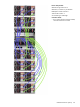
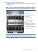


• Switches in interconnect bays 5 and 6 map to the “a” server nodes in device bays 1–16.
(Referred to as servers 1a–16a.)
• Switches in interconnect bays 7 and 8 map to the “b” server nodes in device bays 1–16.
(Referred to as servers 1b–16b.)
Connecting an MDS600 that will be accessed based on “a”
or “b” server type (controlled by connections to same
interconnect row)
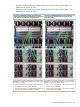
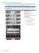
Connecting an MD600 that will be accessed based on
c-Class enclosure device bay (controlled by connections to
same switch ports in different interconnect rows)
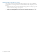
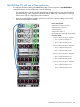
To complete this example configuration, connect the bottom
MDS600 in a similar cabling pattern, but to ports on the
switches in interconnect bays 7 and 8.
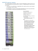
To complete this example configuration, connect the bottom
MDS600 in a similar cabling pattern, but to ports 5 and
6 on the four switches.
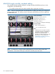
• All “a” servers in device bays 1–16 will have exclusive
access to the top MDS600.
• Servers in device bays 1–8 (both a and b nodes) will
have exclusive access to the top MDS600.
• •Servers in device bays 9–16 (both a and b nodes) will
have exclusive access to the bottom MDS600.
All “b” servers in device bays 1–16 will have exclusive
access to the bottom MDS600.
MDS600 with double-density servers 103