HP StorageWorks 600 Modular Disk System Maintenance and Service Guide Abstract This guide describes identification and maintenance procedures, diagnostic tools, specifications and requirements for hardware components and software. This guide is for an experienced service technician. HP assumes you are qualified in the servicing of computer equipment, trained in recognizing hazards in products, and are familiar with weight and stability precautions.
© Copyright 2008, 2011 Hewlett-Packard Development Company, L.P. The information contained herein is subject to change without notice. The only warranties for HP products and services are set forth in the express warranty statements accompanying such products and services. Nothing herein should be construed as constituting an additional warranty. HP shall not be liable for technical or editorial errors or omissions contained herein. Windows is a U.S. registered trademark of Microsoft Corporation.
Contents Customer self repair ...................................................................................................................... 5 Parts only warranty service ............................................................................................................................ 5 Illustrated parts catalog ............................................................................................................... 16 Mechanical components ..........................................
Acronyms and abbreviations ........................................................................................................ 62 Index .........................................................................................................................................
Customer self repair HP products are designed with many Customer Self Repair (CSR) parts to minimize repair time and allow for greater flexibility in performing defective parts replacement. If during the diagnosis period HP (or HP service providers or service partners) identifies that the repair can be accomplished by the use of a CSR part, HP will ship that part directly to you for replacement. There are two categories of CSR parts: • Mandatory—Parts for which customer self repair is mandatory.
Obligatoire - Pièces pour lesquelles la réparation par le client est obligatoire. Si vous demandez à HP de remplacer ces pièces, les coûts de déplacement et main d'œuvre du service vous seront facturés. Facultatif - Pièces pour lesquelles la réparation par le client est facultative. Ces pièces sont également conçues pour permettre au client d'effectuer lui-même la réparation.
In base alla disponibilità e alla località geografica, le parti CSR vengono spedite con consegna entro il giorno lavorativo seguente. La consegna nel giorno stesso o entro quattro ore è offerta con un supplemento di costo solo in alcune zone. In caso di necessità si può richiedere l'assistenza telefonica di un addetto del centro di supporto tecnico HP. Nel materiale fornito con una parte di ricambio CSR, HP specifica se il cliente deve restituire dei componenti.
defekte Teil nicht zurückschicken, kann HP Ihnen das Ersatzteil in Rechnung stellen. Im Falle von Customer Self Repair kommt HP für alle Kosten für die Lieferung und Rücksendung auf und bestimmt den Kurier-/Frachtdienst. Weitere Informationen über das HP Customer Self Repair Programm erhalten Sie von Ihrem Servicepartner vor Ort. Informationen über das CSR-Programm in Nordamerika finden Sie auf der HP Website unter (http://www.hp.com/go/selfrepair).
enviara el componente defectuoso requerido, HP podrá cobrarle por el de sustitución. En el caso de todas sustituciones que lleve a cabo el cliente, HP se hará cargo de todos los gastos de envío y devolución de componentes y escogerá la empresa de transporte que se utilice para dicho servicio. Para obtener más información acerca del programa de Reparaciones del propio cliente de HP, póngase en contacto con su proveedor de servicios local.
Neem contact op met een Service Partner voor meer informatie over het Customer Self Repair programma van HP. Informatie over Service Partners vindt u op de HP website (http://www.hp.com/go/selfrepair). Garantieservice "Parts Only" Het is mogelijk dat de HP garantie alleen de garantieservice "Parts Only" omvat. Volgens de bepalingen van de Parts Only garantieservice zal HP kosteloos vervangende onderdelen ter beschikking stellen.
No caso desse serviço, a substituição de peças CSR é obrigatória. Se desejar que a HP substitua essas peças, serão cobradas as despesas de transporte e mão-de-obra do serviço.
Customer self repair 12
Customer self repair 13
Customer self repair 14
Customer self repair 15
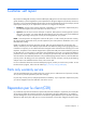
Illustrated parts catalog Mechanical components Item Description Spare part number Customer self repair (on page 5) 1 Chassis — — 2 Internal rail kit 455980-001 No3 3 Hard drive drawer bezel 455973-001 Optional2 4 Power supply blank 441825-001 Mandatory1 5 I/O module blank 463756-001 Mandatory1 Mandatory—Parts for which customer self repair is mandatory. If you request HP to replace these parts, you will be charged for the travel and labor costs of this service.
No: Non—Certaines pièces HP ne sont pas conçues pour permettre au client d'effectuer lui-même la réparation. Pour que la garantie puisse s'appliquer, HP exige que le remplacement de la pièce soit effectué par un Mainteneur Agréé. Ces pièces sont identifiées par la mention “Non” dans le Catalogue illustré. 3 Mandatory: Obbligatorie—Parti che devono essere necessariamente riparate dal cliente.
Illustrated parts catalog 18
System components Item Description Spare part number Customer self repair (on page 5) 6 I/O module with tray and cable 498472-001 Mandatory1 7 Fan 413996-001 Mandatory1 8 Power supply 441830-001 Mandatory1 9 Power block board kit 455975-001 Optional2 a) UID/power switch board with cables — — b) Dual 7-segment display board with cables Power block assembly — — 455974-001 Optional2 a) UID/power switch board — — 10 Illustrated parts catalog 19
Item Description Spare part number Customer self repair (on page 5) b) Dual 7-segment display board — — c) Power supply boards — — d) Power supply/7-segment ribbon cable — — e) Crossover cable — — f) I/O cage assembly — — g) Power/UID bezel assembly — — h) 7-segment rear bezel — — 11 Fan power board with cables 455977-001 No3 12 455976-001 No3 13 Hard drive drawer with hard drive backplane and cables Extension arm with cables 455978-001 No3 14 LED display board with cable
Optional—Parts for which customer self repair is optional. These parts are also designed for customer self repair. If, however, you require that HP replace them for you, there may or may not be additional charges, depending on the type of warranty service designated for your product. 3 No—Some HP parts are not designed for customer self repair. In order to satisfy the customer warranty, HP requires that an authorized service provider replace the part.
Optional: Opcional—Peças cujo reparo feito pelo cliente é opcional. Essas peças também são projetadas para o reparo feito pelo cliente. No entanto, se desejar que a HP as substitua, pode haver ou não a cobrança de taxa adicional, dependendo do tipo de serviço de garantia destinado ao produto. 3 No: Nenhuma—Algumas peças da HP não são projetadas para o reparo feito pelo cliente. A fim de cumprir a garantia do cliente, a HP exige que um técnico autorizado substitua a peça.
Removal and replacement procedures Required tools The following items are required for some procedures: • T-8 Torx screwdriver • T-10 Torx screwdriver • T-15 Torx screwdriver • Phillips screwdriver Safety considerations Before performing service procedures, review all the safety information. Preventing electrostatic discharge To prevent damaging the system, be aware of the precautions you need to follow when setting up the system or handling parts.
WARNING: To reduce the risk of personal injury or equipment damage when unloading a rack: • At least two people are needed to safely unload the rack from the pallet. An empty 42U rack can weigh as much as 115 kg (253 lb), can stand more than 2.1 m (7 ft) tall, and may become unstable when being moved on its casters. • Never stand in front of the rack when it is rolling down the ramp from the pallet. Always handle the rack from both sides. WARNING: The HP MDS600 Disk System is very heavy.
WARNING: A risk of electric shock from high leakage current exists. Before connecting the AC supply to the power enclosures, be sure that the electrical outlets are properly grounded (earthed). CAUTION: Always be sure that equipment is properly grounded and that you follow proper grounding procedures before beginning any installation procedure. Improper grounding can result in ESD damage to electronic components. For more information, see "Preventing electrostatic discharge (on page 23).
3. Extend the hard drive drawer. WARNING: Pinch hazard—Keep hands out of front and rear of chassis when closing hard drive drawers. CAUTION: To prevent improper cooling and thermal damage, do not operate the MDS600 for an extended period of time with the drawer open. Hard drive blank CAUTION: To prevent improper cooling and thermal damage, do not operate the MDS600 unless all bays are populated with either a component or a blank.
2. Remove the hard drive blank. To replace the blank, slide the blank into the bay until it locks into place. Hard drive CAUTION: To prevent improper cooling and thermal damage, do not operate the MDS600 unless all bays are populated with either a component or a blank. Remove a drive only when there is another drive ready to install or the MDS600 is powered down.
2. Remove the hard drive. To replace the component: 1. Fully extend the hard drive lever. 2. Push the hard drive all the way into the drive bay, and then close the lever. Hard drive drawer bezel To remove the component: 1. Power down the MDS600 ("Power down" on page 25). 2. Extend the hard drive drawer (on page 25). 3. To access the screws securing the bezel to the hard drive drawer, remove the hard drives in device bays 2 and 7.
4. Remove the eight T-8 Torx screws securing the bezel to the hard drive drawer. 5. Be sure the drawer handle is in the down position. 6. Lean the bezel forward, and then remove it from the hard drive drawer. To replace the component, reverse the removal procedure. The screws are different lengths. Be sure they are installed in the proper location. Hard drive drawer display board To remove the component: 1. Power down the MDS600 ("Power down" on page 25). 2.
For the location of these device bays, see "Device bay ID numbers (on page 59)." 5. Remove the hard drive drawer bezel ("Hard drive drawer bezel" on page 28). 6. Remove the T-15 Torx screw securing the display board assembly to the hard drive drawer, and then lift the assembly straight up to remove it from the drawer. 7. Turn the display board assembly over, remove the two T-15 Torx screws securing the board to the cover, and lift the board straight out.
8. Disconnect the cable from the display board. To replace the component, reverse the removal procedure. Fan IMPORTANT: Configurations using power cord part number 142263-004, located on the power cord label, require that the power cord be removed before removing a fan. Before removing a fan, do the following: • Verify the status of the fan to be replaced by reviewing rear panel LEDs and buttons (on page 57). • Be sure that your configuration can support your actions.
2. Remove the fan. CAUTION: For best cooling practices, do not operate the enclosure for extended periods with more than one component or blank removed. When removing an active component permanently, replace it with a blank. To replace the fan, install it into the fan bay and push until it locks into place. Hot-plug I/O module Before removing the component, be sure to do the following: • Verify the status of the I/O module to be replaced by reviewing rear panel LEDs and buttons (on page 57).
3. Release the I/O handle, push the I/O handle down until it ejects the I/O module, and then remove the I/O module. CAUTION: For best cooling practices, do not operate the enclosure for extended periods with more than one component or blank removed. When removing an active component permanently, replace it with a blank. To replace the component, reverse the removal procedure. Be sure the I/O module is fully seated and the I/O module handle is in the locked position.
Remove the component as indicated. To replace the component, reverse the removal procedure. Be sure the I/O module blank is fully seated and the I/O module blank handle is in the locked position. Power supply Before removing the component, be sure to do the following: • Verify the status of the power supply to be replaced by reviewing rear panel LEDs and buttons (on page 57). • Be sure that your configuration can support your actions.
2. Remove the component as indicated. To replace the component, reverse the removal procedure. Power supply blank CAUTION: For best cooling practices, do not operate the enclosure for extended periods with more than one component or blank removed. When removing an active component permanently, replace it with a blank. Remove the component as indicated. To replace the component, reverse the removal procedure.
Power block To remove the component: 1. Power down the MDS600 ("Power down" on page 25). 2. Disconnect all cables. 3. Remove all power supplies ("Power supply" on page 34). 4. Remove all fan modules ("Fan" on page 31). 5. Remove all I/O modules ("Hot-plug I/O module" on page 32). 6. Release the hard drive drawers: a. Pull down the handle on the front of the drawer, but do not extend the drawer. b.
7. Loosen the screw securing the power block to the chassis, press down on the release lever, and then slowly pull the power block out 2.54 to 5.08 cm (1 to 2 in). Do not remove the power block any further because the cable management arm is still attached. 8. Disengage the cable management arm lock from each hard drive drawer: a. Pull the mechanism up and then toward the rear of the chassis to disengage it from the locking plate. b. Slide the cable management arm off both locking plates.
9. Slowly remove the power block. The signal and power cables are still attached. 10. While supporting the power block, disconnect the signal and power cables on each side of the power block. To replace the component, reverse the removal procedure. Hard drive drawer To remove the component: 1. Power down the MDS600 ("Power down" on page 25). 2. Disconnect all cables. 3. Remove all power supplies ("Power supply" on page 34). 4. Remove all fan modules ("Fan" on page 31). 5.
CAUTION: To avoid data loss, be sure that the drives are labeled and returned to the same bays they were removed from. 6. Be sure the hard drive drawer is closed completely. 7. Remove all I/O modules ("Hot-plug I/O module" on page 32). 8. Pull down the handle on the front of the drawer, but do not extend the drawer. 9. Push up and hold the two release mechanisms on the I/O bays, and then move the drawer forward about 15 cm (6 in).
11. Extend the hard drive drawer until it clicks. 12. Compress the cable management arm and push toward the drawer to lock it into place.
13. Push in to release the four locking mechanisms on the rails located on the side and bottom of the drawer. 14. Remove the hard drive drawer. To replace the component: 1. Slide the rails back into the chassis. 2. Align the top right edge of the drawer with the flange at the top of the chassis and align the four rails on the left side and bottom of the drawer bay. CAUTION: To avoid damage to the equipment, HP recommends using two people to perform this step.
3. Push the drawer in about 25 cm (10 in). 4. Release the cable management arm and expand to the rear of the chassis. 5. Push the drawer in another 25 cm (10 in). 6. Install the power block ("Power block" on page 36). WARNING: Pinch hazard—Keep hands out of front and rear of chassis when closing hard drive drawers. 7. Install the hard drives. Be sure that the drives are returned to the drive bays they were removed from. 8. Close the drawer. 9. Install all rear panel components. 10.
Fan board To remove the component: 1. Power down the MDS600 ("Power down" on page 25). 2. Disconnect all cables. 3. Remove all power supplies ("Power supply" on page 34). 4. Remove all fan modules ("Fan" on page 31). 5. Remove the hard drives ("Hard drive" on page 27). CAUTION: To avoid data loss, be sure that the drives are labeled and returned to the same bays they were removed from. 6. Be sure that the hard drive drawer is closed. 7. Remove all I/O modules ("Hot-plug I/O module" on page 32).
11. Remove the two T-15 Torx screws securing the fan board to the hard drive drawer, and then remove the fan board, being careful not to disconnect the two cables. 12. Disconnect the cables. To replace the component, reverse the removal procedure. Dual 7-segment display board To remove the component: 1. Power down the MDS600 ("Power down" on page 25). 2. Disconnect all cables. 3. Remove all power supplies ("Power supply" on page 34). 4. Remove the fans ("Fan" on page 31). 5.
6. Remove the power block ("Power block" on page 36). 7. Disconnect the signal cables, remove the four T-15 Torx screws securing the dual 7-segment display board to the power block, and then remove the 7-segment display board. To replace the component, reverse the removal procedure. Power button/UID board To remove the component: 1. Power down the MDS600 ("Power down" on page 25). 2. Disconnect all cables. 3. Remove all power supplies ("Power supply" on page 34). 4.
7. Disconnect the signal cables, remove the four T-15 Torx screws securing the power button/UID board to the power block, and then remove the power button/UID board. To replace the component, reverse the removal procedure. Cable management arm To remove the component: 1. Power down the MDS600 ("Power down" on page 25). 2. Disconnect all cables. 3. Remove all power supplies ("Power supply" on page 34). 4. Remove the fans ("Fan" on page 31). 5. Remove all hard drives ("Hard drive" on page 27).
10. Located behind the cable management arm, remove the T-15 Torx screw that secures the cables to the hard drive drawer, and then remove the cables. 11. Located behind the cable management arm, lift up on the tab to release the latch, and then slide the cable management arm off to remove it. 12. Lay the drawer on its side with the hard drive bays facing down.
13. Remove the 11 screws securing the backplane cover plate. The screws are different sizes. Use the following illustration and table to identify and keep track of the screws. Item Description 1 Flushmount T-10 Torx screws 2 T-15 Torx screws 3 5/8-in T-15 Torx screws 14. Remove the backplane board: a. Remove the thumbscrews securing the backplane board to the drawer. b. Disconnect the LED panel cable. c.
15. Disconnect the cables. When reconnecting the cables, use the following illustration and table to be sure the cables are properly reconnected. Item Description 1 Fan signal cable 2 Red 12V power cable 3 Black GND cable 4 Fan power cable 5 Power signal cable 1. Thread the cables through the opening in the drawer. 2. Remove the cable management arm. To replace the cable management arm: 1. Thread the cables through the opening in the drawer, and then connect them to the backplane board.
CAUTION: To avoid damage to the equipment, be sure that the cables are properly connected. The red cable is 12V. The black cable is GND. 2. Install the backplane board: a. Be sure the board is lined up on the standoffs. b. Install the screws. 3. Connect the LED panel cable. 4. Install the cover. 5. Install the cable management arm. 6. Install the hard drive drawer. 7. Install the hard drives. 8. Close the hard drive drawer. 9. Install all rear panel components. 10. Connect the cables.
Diagnostic tools Integrated Management Log The IML records hundreds of events and stores them in an easy-to-view form. The IML timestamps each event with 1-minute granularity.
For optimum performance, the minimum display settings are 800 × 600 resolution and 256 colors. Servers running Microsoft® operating systems require Internet Explorer 5.5 (with Service Pack 1) or later. For Linux servers, refer to the README.TXT file for additional browser and support information. For more information, refer to the Configuring Arrays on HP Smart Array Controllers Reference Guide on the Documentation CD or the HP website (http://www.hp.com).
Component identification Front panel components Item Description 1 Drawer 1 2 Drawer 1 diagnostic cable access (For use by authorized HP personnel only) 3 Drawer 2 4 Drawer 2 diagnostic cable access (For use by authorized HP personnel only) Diagnostic cable access IMPORTANT: Use of the diagnostic cable connectors is reserved for authorized HP personnel only.
To access the connectors for diagnostic cables, use a small flat-head screwdriver to lift up and release the access tab.
Front panel LEDs and button Item Description Status 1 Hard drive LEDs Normal mode (UID LED is solid) Green = The drive is online, but is not currently active. Flashing irregularly green = The drive is active and it is operating normally. Flashing green (1 Hz) = Do not remove the drive. Removing the drive may terminate the current operation and cause data loss.
Item Description Status 1 Hard drive LEDs Drive locate mode (UID LED is flashing) Green = The drive has been selected by a management application and it is operating normally. Flashing amber (1 Hz) = The drive is not selected and is indicating a predictive failure. Flashing amber/green = The drive has been selected by a management application and is indicating a predictive failure.
Item Description 2 Power On/UID 2 status panel 3 Fan module 1 (Drawer 2) 4 Primary I/O module (Drawer 2) 5 SAS port 1 connector 6 SAS port 2 connector 7 Power supply 3 8 UID 1 status panel 9 Fan module 1 (Drawer 1) 10 Primary I/O module (Drawer 1) 11 SAS port 1 connector 12 SAS port 2 connector 13 SAS port 1 connector 14 SAS port 2 connector 15 Secondary I/O module (Drawer 1) 16 Fan module 2 (Drawer 1) 17 Power supply 4 18 SAS port 1 connector 19 SAS port 2 connector 20
Item Description Status 2 Internal Health LED Green = System health is good. Off = System is off. 3 GSI LED* Amber = Enclosure requires service check: I/O, fan and power supply LEDs, and AC power cables to power supplies. Off = Enclosure is functioning normally. 4 UID button/LED (Drawer 2) Blue = UID LED is enabled from the UID button. Blue flashing = System is in hard drive locate mode or an enclosure firmware update is in progress. Off = UID LED is disabled.
Device bay ID numbers SAS and SATA hard drive LEDs Item Description 1 Fault/UID LED (amber/blue) 2 Online LED (green) Component identification 59
SAS and SATA hard drive LED combinations Online/activity LED (green) Fault/UID LED (amber/blue) Interpretation On, off, or flashing Alternating amber and blue The drive has failed, or a predictive failure alert has been received for this drive; it also has been selected by a management application. On, off, or flashing Steadily blue The drive is operating normally, and it has been selected by a management application.
Specifications Environmental specifications Specification Value Temperature range* Operating 10°C to 35°C (50°F to 95°F) Maximum rate of change is 10º C/hr (50º F/hr) Storage -30°C to 60°C (-22°F to 140°F) Maximum rate of change is 20º C/hr (68º F/hr) Relative humidity** Operating 10% to 90% relative humidity (Rh), 28º C (82.4º F) maximum wet bulb temperature, non-condensing Storage 5% to 95% relative humidity (Rh), 38.7º C (101.
Acronyms and abbreviations ACU Array Configuration Utility ADU Array Diagnostics Utility CPLD complex programmable logic device GSI global service indicator I/O input/output IML Integrated Management Log PIC peripheral interface controller SAS serial attached SCSI SATA serial ATA SES SCSI Enclosure Services SIM Systems Insight Manager UID unit identification Acronyms and abbreviations 62
Index hard drive LEDs 59 hard drives 27 A ACU (Array Configuration Utility) 51 ADU (Array Diagnostic Utility) 51 I I/O module 32 I/O module blank 33 IML (Integrated Management Log) B buttons 53 L C cable management arm 46 cautions 23 components 16, 23, 53 connectors 53, 56 customer self repair (CSR) 5 D device numbers 59 diagnostic cable access 53 diagnostic tools 51 display board, hard drive drawer, removing drive LEDs 59 dual 7-segment display board 44 29 LED, 7-segment display 57 LED, heartbeat
SAS hard drive LEDs 59, 60 SAS/SATA LED combinations 60 SATA hard drive LEDs 59, 60 specifications 61 static electricity 23 system components 19, 53 U utilities 51 W warnings 23 Index 64