HP mc-Series 5042 Rack Options Installation Guide Abstract This document is for the person who installs racks and rack products. This procedure is performed only by trained personnel. HP assumes you are qualified in performing installations and trained in recognizing hazards in rack products.
© Copyright 2012, 2013 Hewlett-Packard Development Company, L.P. The information contained herein is subject to change without notice. The only warranties for HP products and services are set forth in the express warranty statements accompanying such products and services. Nothing herein should be construed as constituting an additional warranty. HP shall not be liable for technical or editorial errors or omissions contained herein.
Contents About this guide ........................................................................................................................... 5 HP mc-Series 5042 Rack options installation guide ........................................................................................ 5 Safety information ..................................................................................................................................... 5 Optimum environment and site preparation .......................
Contents 4
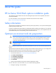
About this guide HP mc-Series 5042 Rack options installation guide This installation guide includes instructions for installing the option kits that are compatible with the HP mc-Series 5042 Rack. For more information, see the HP mc-Series 5042 Rack User Guide on the HP website (http://www.hp.com/go/rackandpower). Safety information The HP mc-Series 5042 Rack is tested to the maximum pressure (PS) of 8 bar (116 PSI) without fluid trapped inside by closed, external valves.
• Lying on top of the floor • Through the top of the MCS 5042 unit For more information on routing the water lines, see the HP mc-Series 5042 Hook Up Kit Installation Instructions.
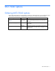
MCS 5042 options Ordering MCS 5042 options HP provides several option kits to complement or complete your MCS 5042 rack. For more information about ordering MCS 5042 options, see the HP website, or contact your nearest HP authorized reseller. MCS 5042 option kit Part number Automatic Door Release Kit (on page 8) Included with the Enables the rack doors to open automatically to maintain MCS 5042 air flow and cooling to the servers in the event of an emergency.
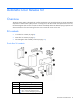
Automatic Door Release Kit Overview The HP mc-Series 5042 is designed with a safety mechanism in the event that the HP mc-Series 5042 Rack experiences a chilled water system pressure or cooling loss. If the MCS 5042 rack experiences such a loss, the electromagnetic locks on the front and rear doors immediately deactivate. Release springs open the rack doors and allow air flow and cooling from the room to reach the servers in the rack.
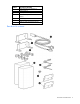
Callout Description (Quantity) 4 Electromagnetic lock assembly (1) 5 Spacer block (1) 6 Strike plate bracket (2) 7 2-inch x 1-inch plastic adhesive-backed strip (1) 8 Washer (4) 9 Electromagnetic lock cable (1) Not shown Adhesive cable management clip (6) Rear door kit contents Automatic Door Release Kit 9
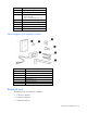
Callout Description (Quantity) 1 Electromagnetic lock bracket (2) 2 Electromagnetic lock cable (1) 3 Mounting hardware (1) • • M5 lock nut (8) M5 x 12-mm flat-head screw (4) 4 Electromagnetic lock assembly (2) 5 Door release spring (2) 6 Strike plate bracket (2) 7 Washer (8) Not shown Cable tie wrap (12) Electromagnetic lock assembly contents Callout Description (Quantity) 1 Magnet (1) 2 Strike plate (1) 3 Rubber washer (1) 4 Roll pin (2) 5 Flathead screw (1) 6 Black cap sc
• M5 socket screwdriver • Allen wrench (included in the kit contents) • Measuring tape A T screwdriver is optional to ease installation. Installing the front automatic door release kit 1. Using a T-30 Torx screwdriver, remove the existing front door lock catches by removing the screw from each of the two front door lock catches. 2. Install the front electromagnetic lock ("Installing the front electromagnetic lock" on page 11). 3.
2. To attach the electromagnetic lock bracket onto the front rack frame, use a T-25 Torx screwdriver to insert and tighten two M5.5 self-taping screws (2). 3. To secure the electromagnetic lock bracket, pull the bracket forward, and then tighten the thumbscrew on the top of the bracket. 4. Position the electromagnetic lock on top of the electromagnetic lock bracket so that the magnetic lock cable connector hangs from the bottom of the assembly.
5. To attach the electromagnetic lock to the electromagnetic lock bracket, use the Allen wrench to insert and tighten two black cap screws. Installing the front strike plate NOTE: The MCS 5042 comes with two different strike plate brackets for the front. One bracket is for the MCS installed with a HP 10642 G2 (1,200 mm deep) IT rack and is labeled with an "A." The other bracket is for the MCS installed with a HP 642 (1,200 mm) deep IT rack and is not labeled.
To install the front strike plate: 1. Using a T-25 Torx screwdriver, remove the two M5.5 x 10-mm screws from the inside of the rack front door. 2. Align the strike plate bracket to the holes on the rack front door. 3. Using a T-25 Torx screwdriver, insert and then tighten the two M5.5 x 13-mm screws to attach the strike plate bracket to the rack. 4. Assemble the strike plate: a. Insert a flathead screw through the strike plate (2). b.
o To install the strike plate in the full lock position, align the strike plate assembly directly to the strike plate bracket, inserting the flathead screw into the third hole from the top of the strike plate bracket. Use the Allen wrench to attach the strike plate assembly to the strike plate bracket by tightening the flathead screw.
4. Using a T-25 Torx screwdriver, insert and tighten two M5 x 10 mm pan head screws into each hole on the door. 5. Close the front door, and then verify that the release spring comes in contact with the frame. 6. Install the plastic adhesive backed strip to the frame by removing the adhesive backing and placing the plastic strip approximately 155 mm (6.1 inches) to the left of the end of the frame.
Installing the front magnetic lock cable 1. Plug the magnetic lock cable into the cable connector hanging from the bottom of the electromagnetic lock assembly.
2. Using the adhesive cable management clips, route the magnetic lock cable up and across the front of the rack to the panel connector on the MCS 5042 rack. 3. Plug the other end of the magnetic lock cable into the panel connector on the transfer switch. 4. Using the remaining adhesive cable management clips, secure any excess cable.
Operation of the front door after installing the automatic door release kit After you have installed the automatic door release kit to the front door of your rack, to avoid mishandling the latch handle of your door, HP recommends that you follow these guidelines when opening your rack front door. 1. Set your magnetic locks into the half lock position. 2. Insert the key into the latch handle of your rack front door, and lock the latch handle. 3.
2. Using a T-25 Torx screwdriver, remove the two M5.5 x 10 mm screws of the top lock plate, and then remove the plate. Installing the rear electromagnetic locks You can install the rear electromagnetic locks using two options. • With the full lock position, you attach the strike plates to the electromagnetic locks directly. This option offers a very high resistance by securing and locking the rear rack doors.
• With the half lock position, you partially attach the strike plates to the electromagnetic locks. This option offers less resistance by only securing, not locking, the rear rack doors. To install the rear electromagnetic locks: 1. Align the electromagnetic lock on top of the electromagnetic lock bracket, routing the magnetic lock cable through the notch on the electromagnetic lock bracket. 2.
electromagnetic lock assembly to the top of the rear rack frame, use a T-25 Torx screwdriver to insert and tighten the two M5.5 self-tapping screws into the inner row of rack holes. 4. Repeat steps 1 through 3 for the bottom, rear electromagnetic lock. Installing the rear strike plates 1. Align the strike plate bracket to the two studs on the top of the rear rack right door. 2.
d. Using the supplied Allen wrench, tighten the flathead screw. 4. Repeat steps 1 through 3 for the bottom, rear strike plate. Installing the rear door release springs 1. Align the door release spring with the studs on the rear right door.
2. Using an M5 socket driver, insert and tighten the two M5 lock nuts over the studs. 3. Close the rear right door and confirm that there is contact with the door release spring. 4. Repeat steps 1 through 3 for the rear left door. Installing the rear magnetic lock cable 1. Plug one end of the magnetic lock cable into the cable connector hanging from the right of the upper electromagnetic lock assembly.
2. Plug the other end of the magnetic lock cable into the cable connector hanging from the right of the lower electromagnetic lock assembly. 3. Using the cable tie wraps, route the magnetic lock cable up the side of the rack to the panel connector on the AC transfer switch. 4. Plug the center connector of the magnetic lock cable into the panel connector on the AC transfer switch. 5. Using the remaining cable tie wraps, secure any excess cable.
Hook Up Kit About this kit Before the delivery of your HP mc-Series 5042 Rack, you must install this kit to your facility water line at the location of your MCS 5042 unit installation. For location recommendations, see the HP mc-Series 5042 Rack Site Preparation Guide on the HP website (http://www.hp.com/go/rackandpower).
Required tools • Two pipe wrenches • 5-mm HEX L-key (included in your kit contents) • (Optional) Hacksaw • T-25 Torx screwdriver • T-30 Torx screwdriver • Phillips screwdriver (Optional) Installing additional components to your facility water line You can install the HP mc-Series 5042 Hook Up Kit in several configurations.
For easy installation, connect the end with the clam shell to your facility. Routing the hose through the MCS 5042 Determine how you will install the main hoses: • Through an opening in the raised floor For more information, see "Attaching the main hoses to the MCS 5042 through an opening in the raised floor (on page 31).
For more information, see "Attaching the main hoses to the MCS 5042 above the floor (on page 32).
For more information, see "Attaching the main hoses to the MCS 5042 through the top of the unit (on page 33)." Installing the 90° elbow assembly 1. Insert the Viton gasket into the swivel nut of the union at the 90° elbow assembly. 2. Hold the 90° elbow in the designated direction (towards the top for installation through the top of the unit, or towards the bottom for rear or bottom installation), and hand-tighten the 90° elbow assembly to the MCS 5042 unit.
3. Use two wrenches to tighten the union an additional two flats. Be sure the direction of the elbow does not change. Attaching the main hoses to the MCS 5042 through an opening in the raised floor 1. Route the main hose through the opening in the raised floor at the opening in the bottom of the MCS 5042. 2. Run the hoses up and connect them to the 90° elbow assembly. 3. Hand-tighten the hoses to the 90° elbow assembly.
Callout Component B hose—Outlet Main water hose—Inlet Brings cold water into the MCS 5042 4. Function Use a pipe wrench to tighten the hose connections an additional two flats. Attaching the main hoses to the MCS 5042 above the floor 1. Using a T-30 Torx screwdriver, remove the two screws securing the bottom rear panel to the unit. Save the screws. 2. Re-use the screws to install the rear plate with the cutout facing the unit. 3.
6. Using a pipe wrench, tighten the hose connections an additional two flats. Attaching the main hoses to the MCS 5042 through the top of the unit 1. Using a T-30 Torx screwdriver, remove the four screws securing the top panel to the unit. Save the screws. 2. Re-use the screws to install the top plate with the cutout facing the unit. 3. Route the main hose through the opening in the top plate into the MCS 5042. 4. Run the hoses down, and connect them to the 90° elbow assembly. 5.
7. Using a T-25 Torx screwdriver and the eight M5.5 x 10 self-tapping screws from this kit (four screws per bracket), secure the two support brackets to the rear frame in approximately equal distances between the hose connections in the MCS 5042 and the top plate. 8. Open the clamps and insert the hoses. Insert the screws that came with the clamps from the front of the MCS 5042 to the back, and use a Phillips screwdriver to secure the hoses into the clamps. (Optional) Shortening the hoses 1.
2. Remove the clam shell clamp from around the hose and remove the swivel nut from the end of the hose. 3. Using a hacksaw, cut the end of the hose to the desired length. 4. Insert the swivel nut into the end of the hose and then replace the clam shell clamp around the hose. NOTE: The shorter screws do not reach the threads of the clam shell until the clam shell is tightened.
5. Insert the four longer M6 screws included in the kit to secure the clam shell clamp around the hose. 6. Using the L-key, tighten the longer M6 screws one turn at a time, tightening all four screws evenly. The clamp must be tight enough for the four shorter M6 screws to reach. 7. One hole at a time, replace the longer M6 screws with the original shorter M6 screws. 8. When you have replaced all four longer M6 screws with the original shorter M6 screws, use the L-key to fully tighten each screw.
2. Use the hose wrench, included in the kit contents, to tighten an additional two flats. (Optional) Attaching the warning label to the hose NOTE: The warning label reminds you: Water will drain when disconnected from the facility piping. If your hoses require additional insulation, attach the warning labels to the insulated hoses.
Rack Expansion Kit About this kit The HP Expansion Rack Kit enables you to connect a secondary rack of the same height and depth to your MCS 5042. When the expansion rack is installed, the MCS 5042 cools both racks.
Installing the expansion rack 1. Using a T-30 Torx screwdriver, remove the eight M6 screws securing the MCS 5042 one-piece side panel, and then remove the panel from the MCS 5042. 2. Using a T-30 Torx screwdriver, remove the three side panel mounting brackets.
3. To remove the panel that covers the cutout on the rear extension kit of the MCS 5042, remove the eight (seven shown in the following illustration) thumb screws. 4. Attach the gaskets, included in your kit contents, to the MCS 5042: a. Remove the liner backing from each gasket. b. Attach the two 1130-mm gaskets to the top and bottom frames on the side of the MCS 5042. c. Attach the three 1870-mm gaskets to the front, middle, and rear of the side of the MCS 5042.
d. Attach the 4040-mm gasket around the cutout of the rear extension. 5. Position the expansion rack next to the MCS 5042 where it will be bayed, ensuring that the rack feet are on solid flooring. 6. Use an adjustable wrench to adjust each leveling foot of the expansion rack, ensuring that the rack is level with the MCS 5042.
7. Pull the pins on the four hinges of the left rear door on the expansion rack, and then remove the door. 8. Open the front and rear doors of the MCS 5042 to access the baying bracket holes. 9. Install the six baying brackets, included in your kit contents, between the MCS 5042 and the expansion rack. You must install the brackets in the same holes where you removed the side panel brackets.
b. From the front of the rack, repeat the preceding step for installing the brackets in the rear of the rack. 10. Replace the rear door of the expansion rack: a. Align the door to the four hinge locations on the rack frame. b. Squeeze the two pins on each hinge, and then insert each hinge into the hinge bracket. 11. Install the side panel removed from the MCS 5042 to the open side of the expansion rack. 12.
a. Remove the small connector from the front door sensor in the MCS 5042.
b. Using one of the door sensor cables included in the expansion rack, plug one side to the front door sensor in the MCS 5042. c. Route the cable through the MCS 5042 behind the management module to the expansion rack.
d. Plug the other end of the cable into the bottom of the second front door sensor in the expansion rack.
e. Use the cable ties in the kit to secure the cable and wind up any excessive cable. 13. Install the rear door sensor cable: a. Remove the small connector from the top connection of the rear door sensor in the MCS 5042.
b. Using the other side of the door sensor cables included in the expansion rack, plug one side to the front door sensor in the MCS 5042. c. Route the cable through the rear of the MCS 5042 behind to the expansion rack. d. Plug the other end of the cable into the bottom of the second front door sensor in the expansion rack. e. Use the cable ties in the kit to secure the cable and wind up any excessive cable. f. 14.
Installation is complete.
Acronyms and abbreviations MCS modular cooling system Acronyms and abbreviations 50
Documentation feedback HP is committed to providing documentation that meets your needs. To help us improve the documentation, send any errors, suggestions, or comments to Documentation Feedback (mailto:docsfeedback@hp.com). Include the document title and part number, version number, or the URL when submitting your feedback.