HP mc-Series 5042 Rack Site Preparation Guide Table of contents Preface ............................................................................................................................................... 2 Safety and regulatory information .......................................................................................................... 2 Notational conventions .........................................................................................................................
Preface Safety and regulatory information For your protection, this product has been tested to various national and international regulations and standards. The scope of this regulatory testing includes electrical/mechanical safety, radio frequency interference, acoustics, and known hazardous materials. Where applicable, approvals obtained from third-party test agencies are shown on the product label.
Safety in material handling Warning: Do not lift the cabinet manually. To avoid physical injury you must use a mechanical lifting device. Warning: Use care when working with hazardous voltages. This equipment might be configured with dual input line sources. Hazardous voltages and energy might be present even after the removal of a single input source. Trained service personnel must follow the service guidelines. Verify that the differences in ground sources meet LAHJ.
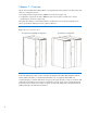
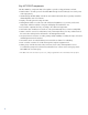
Chapter 1: Overview The HP mc-Series 5042 Rack (“MCS 5042”) is a supplemental cooling system for the data center that offers two configuration options: • Preconfigured with a single HP 642 1200mm IT rack enclosure (Figure 1A) • Configured to support two HP 642 1200mm IT rack enclosure (The second IT rack is a fieldinstalled option, as shown in Figure 1B).
Product overview The MCS 5042 is a modular, distributed cooling solution that removes the high levels of heat generated by current advanced server and mass storage systems. The MCS 5042 provides a uniform, effective, affordable, and distributed cooling approach for servers and other IT equipment installed in server racks.
Key MCS 5042 components The MCS 5042 key components that work together to provide cooling performance include: • Main breakers—Provides power for the MCS 5042 through circuit breakers (do not control power at the input panel*). • Heat Exchanger Module (HEX)—Includes an air-to-water heat transfer device specially created for demanding data center environments. • Display—Provides general cooling unit status.
Figure 3: MCS 5042 component locations Item Reference 1 Cooling unit 2 User display 3 IT rack Item Reference 1 Condensation pump 2 Condensation pump controller 3 Control valve 4 Flow meter 5 Humidity sensor 6 Rear extension 7 Heat exchanger unit 8 Fan units 9 Management module 7
Item Reference 1 Water module 2 Fan module 3 AC transfer switch
MCS 5042 specifications Physical specifications Table 1: MCS 5042 physical specifications of a standard single rack and server cabinet configuration Parameter Packaged system (as shipped on pallet) Unpackaged system (off pallet, unwrapped) Unpackaged CTO system Height 2285 mm (90 in) 2007 mm (79 in) 2007 mm (79 in) Width 1219 mm (48 in) 904 mm (35.6 in) 904 mm (35.6 in) Depth 1829 mm (72 in) Weight 732 kg (1614 lb) 1 1510 mm (59.5 in) 1510 mm (59.
Chapter 2: Facility planning for MCS 5042 implementation Overview The MCS 5042 offers an incremental data center cooling solution, capable of cooling 50 kW of heat from one IT rack or two IT racks. The two basic methods to deploy the MCS 5042 are as a standalone unit or placed in a row adjacent to other MCS 5042 or standard equipment racks. In planning water supply and design, take into consideration short-term and long-term needs for cooling.
Space and positioning considerations The MCS 5042 is larger (and, when fully populated, heavier) than a standard 19-inch equipment rack. Therefore, space required for maneuvering, operating, and servicing the MCS 5042 is greater than standard-sized racks. Delivery space requirements You must ensure the facility has adequate space to receive and remove the MCS 5042 from the shipping pallet.
Figure 4 shows the maneuvering space required when unloading the MCS 5042 from a pallet. When planning for moving the rack, use the delivery forms provided in Appendix A. Figure 4: MCS 5042 shipping package delivery and maneuvering space requirements for a single IT rack configuration Item 1 2 3 Reference MCS 5042 shock-pallet 3 piece ramp HP mc-Series 5042 Rack Caution: HP recommends that a ramp angle of no greater than 5° be used to move the MCS 5042 up or down elevations.
Figure 5 shows the maneuvering space required when unloading the HP MCS 5042 Expansion Rack Kit (BW973A, available on the HP website at http://www.hp.com) from a pallet. When planning for moving the rack, use the delivery forms provided in Appendix A.
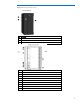
Operational space requirements To provide space for internal airflow and housing of the cooling unit components, the MCS 5042 is wider and deeper than conventional HP racks. HP recommends a minimum access space for the MCS 5042 in the standard single rack configuration be 1219 mm (4 feet) in the front and 914mm (3 feet) in the rear as shown in Figure 6. Figure 6: MCS 5042 operational space dimensions Note: With the top shipping bracket the total height is 2069mm (81.5 inches).
An HP MCS 5042 installed in a dual rack configuration requires approximately an additional 600 mm of width space to accommodate the second IT rack mounted to the left of the cooling unit, as shown in Figure 7. Figure 7: MCS 5042 operational space dimensions in a dual-rack configuration System positioning The MCS 5042 can be installed next to an existing or new row of HP Intelligent Series racks.
Figure 8: MCS 5042 arranged in a flush front configuration with a HP Intelligent Series rack row 8A: Flush front configuration 8B: Flush rear configuration Note: When arranging the MCS 5042 immediately next to a HP Intelligent Series rack, front or rear door swing might interfere, depending on the configuration. Equipment might require the removal of a door for full, unimpeded access.
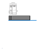
Figure 9: MCS 5042 cable openings in a single rack configuration 9A: Top view 9B: Bottom view 17
Figure 10 shows the size and position of the cable openings in a dual-rack configuration at the top and at the bottom.
Cabinet leveling feet The MCS 5042 system includes leveling feet and does not require fastening to the floor. To ensure the enclosure remains stable during operation and servicing and to avoid personnel and equipment damage, take care when the loading of the equipment. Warning: Static loading limits cannot be achieved if the rack is not on its leveling feet, and rolled or pushed from its position. Your floor weight capacity might not support the full static load capacity.
Figure 11: Cabinet leveling feet locations in a single-rack configuration 11A: Bottom view 11B: IT rack-side view 20
Figure 12: Cabinet leveling feet locations in a dual rack configuration 12A: Bottom view 12B: Right IT rack-side view Floor loading considerations The computer room floor must be able to support the total weight of the installed servers as well as the weight of the MCS 5042 as they are moved into position. The information presented in this section is applicable to raised floor installations.
Warning: HP cannot assume responsibility for determining the suitability of a particular raised floor system. The customer or local agencies must determine installation requirements. An appropriate structural engineer must verify any floor system under consideration for a server installation. Raised floor loading is a function of the floor manufacturer’s load specification and the positioning of the equipment relative to the raised floor grid.
Table 5: Tate All Steel 1250 raised floor specifications Item Rating Dead load 34.2 kg/m2 (7 lb/ft2) Design load Rolling load 1 1 567 kg (1,250 lb) 227 kg (500 lb) Similar to concentrated load Note: The IT rack of the MCS 5042 can carry a static load of up to 1,360 kg (3,000 lb). Note: In Figures 13 and 14, the load is in the center of the IT racks. Due to adjacency, the leveling feet in points B and E in Figure 13 and points B, C, F, and G in Figure 14 are combined to one concentrated weight.
Figure 14: Weight distribution on the leveling feet locations in a dual rack configuration A B C D E F G H Weight 385 kg (849 lb) 455 kg (1003 lb) 458 kg (1010 lb) 385 kg (849 lb) 375 kg (827 lb) 457 kg (1007 lb) 457 kg (1007 lb) 375 kg (827 lb) Caution: To reduce the risk of damage to the casters, make sure that the full weight of the rack rests on the leveling fee, and not on the casters. The casters are designed only as an aid in moving the rack into position.
Note: The power requirements discussed in this guide are for the fans and electronics for the MCS 5042 only. Data processing components such as servers, storage, and network devices must be considered separately, based on individual power requirements. System grounding HP server systems require two methods of grounding: power distribution grounding for safety, and high-frequency signal grounding for equipment performance.
Figure 16: Raised floor grounding Voltage fluctuations and outages The MCS 5042 is designed to provide immunity to power outages of less than one cycle. However, testing cannot conclusively rule out loss of service. Therefore, adherence to the following guidelines provides the best possible performance of power distribution systems for HP equipment: • Dedicated power source—Isolates the power distribution system from other circuits in the facility.
Electrical planning around water handling components Because of the potential of forming condensate on non-insulated water connections or leaking water connections around water-based cooling systems, a few issues must be considered during the electrical planning: • Water-proofed connectors • Watertight conduits for cables • Leak detection systems Warning: If water comes in contact with power cables, before cleaning up water in this area, shut down the main breaker.
Note: The power cords of the MCS 5042 are 4 m (13.1 feet) long. After the cords are connected to the MCS 5042 and routed down the rear of the IT rack, approximately 2 m (6.6 feet) will be left to connect to the power source. When using only a single (primary) source for power, the AC power cord is connected to the left-most receptacle (when viewed from the rear of the cabinet, labeled as AC1) as shown in Figure 18.
Coolant source planning A number of factors relating to a chilled water distribution system must be considered during the site preparation process, including the following: • Redundant water configurations (For more information, see Appendix B.
Figure 20 illustrates the MCS 5042 being supplied directly by a dedicated chiller unit or water-towater heat exchanger in a closed loop configuration.
HP recommends the HP mc-Series 5042 Rack Water Hook-up Option Kit BW971A (available on the HP website at http://www.hp.com) for connecting the MCS 5042 to a facility chilled water system. Each kit (Figure 21) includes the hoses and accessories required for connecting the facility supply and return lines to the main inlet and outlet connections of an MCS 5042 unit and must be installed prior to the delivery of an MCS 5042.
Figure 22: Main coolant line hookup options for the MCS 5042 A: Through raised floor cutouts B: Above the floor C: Above the unit 32
An HP Water Hook Up Kit must be installed prior to activating an MCS 5042. The length is approximately 350 cm (138 inches) of flexible hose terminated with fittings at each end. The length that is available outside the MCS 5042 depends on the type of connection that is desired as shown in Figure 22.
Note: Installation service for this MCS 5042 is order number UE005E. Piping approaches HP recommends the following methods for facility plumbing orientation with the MCS 5042: • Direct rear approach • Left rear approach • Right rear approach Note: You can approach the MCS 5042 from the front with piping for the top and bottom connection. However, this approach requires careful planning for accessible component locations and hose attachments.
MCS 5042 hose openings Figure 25 shows the dimensions and locations of the various hoses openings of the MCS 5042.
Raised floor cutouts for MCS 5042 A complete MCS 5042 installation typically requires the following floor cutouts in a raised-floor facility: Standard rack configuration: • One floor cutout for the chilled water hoses, drain hoses of the cooling unit • One floor cutout for the power cords and data cables of the computer equipment rack (including power supply to the MCS 5042). For details on the top openings, see the section Cable openings.
Figure 26: Recommended floor cutouts (single rack configuration)—Option 1 (MCS 5042 cooling unit side flush to tile) Note: The wider opening in the back of the IT rack is optional. Note: The floor tile sizes used in Figure 26 are 600 mm x 600 mm (23.6 inches x 23.6 inches). Floor tile sizes vary. Note: The allowable tolerances are +/- 3.2 mm (+/- 0.125 inches). When installing multiple MCS 5042 units in a row, you must consider the tolerances as you plan the cutouts.
Figure 27: Recommended floor cutouts (single rack configuration)—Option 2 (MCS 5042 rack side flush to tile) Note: The wider opening in the back of the IT rack is optional. Note: The floor tile sizes used in Figure 27 are 600 mm x 600 mm (23.6 inches x 23.6 inches). Floor tile sizes vary. Note: The allowable tolerances are +/- 3.2 mm (+/- 0.125 inches). When installing multiple MCS 5042 units in a row, you must consider the tolerances as you plan the cutouts.
Figure 28: Recommended floor cutouts (dual rack configuration)—Option 1 (Left rack side flush to tile) Note: The wider opening in the back of the IT rack is optional. Note: The floor tile sizes used in Figure 28 are 600 mm x 600 mm (23.6 inches x 23.6 inches). Floor tile sizes vary. Note: The allowable tolerances are +/- 3.2 mm (+/- 0.125 inches). When installing multiple MCS 5042 units in a row, you must consider the tolerances as you plan the cutouts.
Figure 29: Recommended floor cutouts (dual rack configuration)—Option 2 (Right rack side flush to tile) Note: The wider opening in the back of the IT rack is optional. Note: The floor tile sizes used in Figure 29 are 600 mm x 600 mm (23.6 inches x 23.6 inches). Floor tile sizes vary. Note: The allowable tolerances are +/- 3.2 mm (+/- 0.125 inches). When installing multiple MCS 5042 units in a row, you must consider the tolerances as you plan the cutouts.
Chilled water system components The chilled water supply and return service to each MCS 5042 is required to have a particular combination of components for optimal performance. These components are identified in Figure 30 and described in Table 7. Note: Components in Figure 30 drawn with a solid line are strongly recommended. Components drawn with dot lines are advisable for a higher availability and serviceability.
Table 7: Typical plumbing components for a MCS SL4042 configuration Item Description Specifications 1 Chilled water return line Pipe:31.75 mm(1.25 inch), ASTM B 88, Type L, hard-drawn copper Fittings: ASTM B16.22 Wrought copper Solder: ASTM B 32, 95-5 Tin Antimony Thread Sealant: Seal and assemble according to local materials and practices 2 Flow/measurement balancing valve Valve type: 31.75 mm (1.
Item Description Specifications Hannifin, FBMB8-1/4 Metrulok fitting, Festo QB-1/4-5/16-U or equivalent and installed by plumbing contractor, typical 1. 14 Hose barb Type: 12.7 mm (0.50 inch) I.D. hose barb x ¾-inch male NPT, Parker Hannifin, 125HBL-8-12, fitting or equivalent and installed by plumbing contractor, typical 1. 15 Hose Type: 8 mm (0.31 inch) outer-diameter (O.D.) flexible hose supplied with MCS 5042. 16 Hose Type: 9 mm (0.35 inch) inner diameter flexible hose supplied with MCS 5042.
Note: HP recommends that the HP mc-Series 5042 Hook Up Kit (BW971A) be ordered for each MCS 5042 to be installed. Coolant requirements General thermal requirements Table 8: Facility coolant requirements Parameter Value Allowable operational chilled water temperature Minimum Maximum 1 Maximum heat load (50kW) operational chilled water temperature 7°C (45°F) Min. 18°C (64°F) Max 1 Minimum Maximum 7°C (45°F) Min.
You must perform several steps to determine the coolant requirements and corresponding resources necessary for effective implementation of the MCS 5042. The flowchart in Figure 31 outlines the steps and necessary information/resources for each aspect of the implementation. Figure 31: Coolant implementation flow chart for one rack Cooling loop sizing Sizing the cooling loops can be straight forward based on the planned cooling requirements of each populated/planned MCS 5042 server enclosure.
Table 9: Rack Cooling Loop Sizing Chart Installed Component Quantity Max. Watts Generated Max. CFM Required Max. Watts Total Max. CFM Total Component 1: Component 2: Component 3: Component 4: Component 5: Component 6: Component 7: Component 8: Component 9: Component 10: Total for Cabinet 1 1 An approximate value can be estimated by assuming all power entering the cabinet is converted to heat.
Determining heat load capacities The total airflow required by the equipment installed in each server rack must be compared with the total available supply from the MCS 5042, so it is not exceeded. The fans in the MCS 5042 are speed controlled to reduce the airflow in case the maximum cooling capacity is not demanded from the MCS 5042. Table 10 provides a few examples of the approximate fan speeds by the demanded cooling capacity from the MCS 5042.
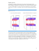
Figure 32: MCS 5042 coolant flow requirements with 20°C (68°F) server intake air 48
Figure 33: MCS 5042 coolant flow requirements with 25°C (77°F) server intake air The following pressure drop chart in Figure 33 is provided as a reference indicating water flow versus the water pressure for a fully-opened MCS 5042 water control valve.
Figure 34: Flow rate versus delta pressure (water control valve fully open) A minimum water pressure difference of 1.0 to 1.5 bar (15 to 20 psi) between facility supply and return is required. Figure 34 gives the pressure difference with a fully opened control valve. In operation the control valve is maintaining the water flow to the MCS 5042 by introducing pressure resistance to reduce the flow to accommodate different water temperatures and cooling capacity.
Water quality requirements Closed-loop water must not contain any lime scale deposits or loose debris. The water must have a low level of hardness, particularly a low level of carbon hardness. Filters must be used to remove free floating particulates and regularly maintained. Additionally, the water must not be so soft that it corrodes the materials that it comes into contact. You must periodically add new fresh water, but also you to remove some of the enriched water.
Another consideration for water is the required set point. Temperatures near or below 0°C (32°F) indicate that the chilled water plant condenser is very close to or below the freezing point of the water. (The minimum chilled water temperature to be supplied to the MCS 5042 is 7°C or 45°F.) This temperature might cause a blockage and damage to the unit, so an additive like glycol might be necessary to lower the freezing point.
Environmental considerations Table 13: Recommended environmental specifications Parameter Value Room Temperature Recommended Minimum/Maximum 18°C (64.4°F)/27°C (80.6°F) Allowable Minimum/Maximum 15°C (59°F)/32°C (90°F) Humidity: Recommended Minimum 5.5°C (41.9°F) dew point Recommended Maximum 60% relative humidity and 15°C (59°F) dew point Allowable range 20%–-80% Note: The temperatures stated are for an elevation of 0 to 5000 feet above sea level.
Appendix A Forms and checklists Delivery survey form The delivery survey form (Figure 35) lists delivery or installation requirements. If any of the items on the list apply, enter the appropriate information in the areas provided on the form. Special instructions or recommendations must be entered on the special instructions or recommendations form.
Pre-installation checklists Site preparation checklist Table 14 is a site preparation checklist. For each item, check Yes or No in the appropriate column. If answering No, include a comment and the date. A No answer means that an alternative might be required.
Item Area/ condition Yes Cooling considerations 24 Can the room temperature be maintained between the recommended 18°C (64.4 °F) Min. –27°C (80.6 °F) Max. and allowable 15°C (59 °F) Min. –32°C (90 °F) Max. (up to 5000 ft) Derate 1°C/1000 ft above 5000 ft and up to 10,000 ft 25 Can humidity level be maintained at the recommended level of 5.5°C (41.
Appendix B: Conversion factors and formulas The conversion factors provided in this appendix are intended to ease data calculation for systems that do not provide information in the format requested in this Site Preparation Guide. The following list includes the conversion factors used in this document, as well as additional conversion factors that might be helpful in determining those factors required for site planning. Conversion factors for refrigeration • 1 watt = 0.86 kcal/hour • 1 watt = 3.
Glossary Table 15: Terms and abbreviations Term Description Apparent power A value of power for AC circuits that is calculated as the product of RMS current times RMS voltage, without taking the power factor into account. ASL Above sea level Btu/hr British thermal units per hour. The amount of heat required to raise one pound of water 1°F/hr, a common measure of heat transfer rate. CFM Cubic feet per minute, commonly used to measure the rate of air flow in an air-conditioning system.
Term Description Typical power consumption Represents the expected power consumption of a given configuration. The typical value is the approximate power consumption that a customer will most likely experience and can use for power budgeting purposes. Watt A standard unit of power defined as one Joule of energy transferred or dissipated in one second.
Legal notices The information in this document is subject to change without notice. HP makes no warranty of any kind with regard to this manual, including, but not limited to, the implied warranties of merchantability and fitness for a particular purpose. HP shall not be held liable for errors contained herein or direct, indirect, special, incidental or consequential damages in connection with the furnishing, performance, or use of this material.