HP Modular Cooling System 200/100 Web Interface User Guide Abstract This document is for the person who installs, administers, and troubleshoots servers and storage systems. HP assumes you are qualified in the servicing of computer equipment and trained in recognizing hazards in products with hazardous energy levels.
© Copyright 2013 Hewlett-Packard Development Company, L.P. The information contained herein is subject to change without notice. The only warranties for HP products and services are set forth in the express warranty statements accompanying such products and services. Nothing herein should be construed as constituting an additional warranty. HP shall not be liable for technical or editorial errors or omissions contained herein. Confidential computer software.
Contents Overview ..................................................................................................................................... 5 Introduction .............................................................................................................................................. 5 Web interface requirements .............................................................................................................. 5 Web interface .............................................
Obtaining replaceable parts ..................................................................................................................... 50 Acronyms and abbreviations ........................................................................................................ 51 Documentation feedback ............................................................................................................. 52 Index .....................................................................................
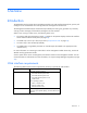
Overview Introduction The HP Modular Cooling System has a management module with a web interface that analyzes, queries, and manages various measurements and warning and alarm messages from the MCS unit. The management module analyzes measurements provided by the cooling unit, generates any necessary warning or alarm messages, and sends the messages to the web interface.
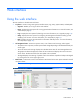
Web interface Using the web interface The web interface is divided into three frames: • • • Top frame—Contains a Sign Out hyperlink and the Home, Logs, Setup, System Name, and Help tabs. o Sign OutEnables you to log out of the web interface. o HomeDisplays the menu options for viewing general status information. For more information, see "Home tab (on page 8)." o LogsDisplays the menu options for data logs. For more information, see "Logs tab (on page 19).
Active Alarms and Legend display panel Each tab in the web interface contains an Active Alarms and Legend display panel. When the MCS unit experiences a critical, warning, normal, unknown, or informational event, the icon corresponding to the event appears in the Active Alarms display panel. The alarm descriptions appear in the Alarms menu, as well as in the Alarm History menu (on page 20).
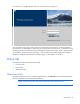
For instructions on changing the password, see "Accounts menu (on page 36)." Only one Admin session and one User session are supported at a time. Sessions can be terminated if a second session is initiated (after successful login) or if a console session timeout occurs. In both situations, the existing session is terminated and the login screen appears. Admin session logins, logouts, and terminations are recorded in the Event Log menu (on page 21).
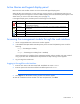
Parameter Function Server Intake Temperature Displays the average server intake temperature Server Exhaust Temperature Displays the average server exhaust temperature Cooling Displays the heat removed by the water Water Inlet Temperature Displays the temperature of the water coming into the MCS unit to be used to cool the servers Water Outlet Temperature Displays the temperature of the water after removing the server heat Water Flow Displays the water flow rate in liters or gallons per minute
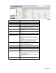
Alarms menu Click Alarms in the left navigation frame to display the Alarms screen. The active alarms are listed by the date and time at which the alarm most recently occurred. The active alarm is removed from the Alarms screen when cleared but is recorded in the Alarm Log. The following information appears for each alarm: • Severity—An icon indicating the severity or status of the alarm (Critical, Warning, Normal, Unknown, or Information). • Description of Alarm—The name of the alarm.
1. Remove the fan unit. 2. Reinstall the same fan unit. If the warning message does not clear after the module is reseated, replace the fan unit with a CSR part. For more information on CSR parts, see "Replaceable parts and maintenance and service information (on page 50).
Indicators Meaning Operator display alarm message Water Temperature In Failed Web interface alarm message Water Unit Temperature Input Out of Range Condition Water temperature sensor is not working properly (possible open circuit). Sensors Water group sensor SNMP notification Warning Type of message Warning Solution: 1. Verify the water supply. 2. Verify whether the water temperature is below or above the water temperature expected range. 3. Contact your building supervisor. 4.
Indicators Meaning Operator display alarm message Water Valve? Web interface alarm message Water Valve Failed Condition Water flow valve is closed, and water flow is detected. Modules Water group SNMP notification Warning Type of message Warning Solution: 1. Verify that the water valve is closed. 2. Contact HP, or see the HP website (http://www.hp.com).
Indicators Meaning Web interface alarm message Temperature too high Condition Heat overload condition Modules or sensors The average server air temperature is above the temperature assigned in the web interface Intake Temp tab High Temperature Threshold field. SNMP notification Critical Type of message Alarm Solution: 1. Verify the water inlet temperature. 2. Verify that the water flow matches the specifications required for the heat load. 3.
Indicators Meaning Operator display alarm message Temperature is too low Web interface alarm message Temperature is too low Condition The average server air temperature is lower than the temperature assigned in the web interface Intake Temp tab (on page 22) Low Temperature Threshold field. Sensors Air temperature sensor SNMP notification Warning Type of message Warning Solution: 1. Verify that the water flow matches specifications required for the heat load. 2.
Indicators Meaning Modules or sensors Server Intake Temperature, Water Flow Meter SNMP notification Critical Type of message Alarm Solution: 1. Verify the water supply and that the MCS unit is receiving water. 2. Verify that the water pressure delta is accurate. 3. Verify that the water flow loss emergency door opening temperature threshold is not less than 5°C (9°F) or more than 20°C (36°F) above the Server Intake Temperature Set Point. 4.
Indicators Meaning Condition The water level has exceeded the permissible level of the condensation pump sensor. Modules or sensors Condensation pump sensor SNMP notification Warning Type of message Warning Solution: 1. To determine the cause, look for leaks or condensation. 2. If no leaks are found, adjust the temperature in the Excessive Moisture: Condensation Pump Cycles Warning Threshold field. IMPORTANT: Use caution when entering temperatures in the Condensation Pump Threshold fields.
NOTE: To clear the condensation pump cycles warning, click Cooling System in the left navigation frame to access the Cooling System screen, and then click the Alarms/Warnings tab. Under the Warnings section, set Alarm Reset to Manual and click Save Settings. Then, return to the General menu and click Clear Alarms. This step only clears the warning when the condensation pump is not running. Both doors are open Indicators Meaning Operator display alarm Both front and rear rack doors are open.
You can enter or change the system name, system contact, and system location information in the System Information tab (on page 31). You can change the IP address in the Network menu (on page 30). NOTE: The following screen is the same for either MCS-100 or MCS-200 units.
Access tab (on page 33). The alarm.history and event.log files are located in the download directory. Every file uploaded and downloaded using FTP is recorded in the FTP.log, which is also located in the download directory. To enable FTP, see the "Remote Access tab (on page 33)." To view FTP Admin and FTP User privileges and assign passwords to open each account, see the "Accounts menu (on page 36)." Alarm History menu To display the Alarm History screen, in the left navigation frame, click Alarm History.
• To update the screen with current log information, click Refresh. Event Log menu To display the Event Log screen, in the left navigation frame, click Event Log. The events are listed by the date and time at which the event most recently occurred. The following information is displayed for each event: • Severity—An icon indicating the severity or status of the alarm (Critical, Warning, Normal, Unknown, or Information). • Description of Event—The name of the event.
• General menu (on page 28) • Network menu (on page 30) • Management menu (on page 31) • Accounts menu (on page 36) • Configuration Save/Restore menu (on page 37) These menu options enable the Admin to configure the settings for the management module. The Setup tab and all menu options are not available to User accounts. Cooling System Click Cooling System in the left navigation frame to access the Cooling System screen.
4. In the Low Temperature Threshold field, enter an air temperature at which an alarm is issued and a trap is sent if the server intake temperature drops below the value listed. The temperature fields specific to the Emergency Door Opening are only visible if the Emergency Door Opening function is enabled. For more information, see Automatic Door Release Kit (on page 26). 5.
Alarms/Warnings tab This screen enables the Admin to change alarm and warning settings for the management module. NOTE: The following screen is the same for either MCS-100 or MCS-200 units. To change the alarm and warning settings: 1. 2. 3. Select to enable or disable the alarm relay from the Alarm Relay radio buttons. This setting affects all alarms and warnings, except for the Server Intake Temperature. o Select Enable to allow the alarm relay when a temperature alarm is generated.
When the MCS unit is in Auto mode, the Fan Speed Target and Water Valve fields are not active. NOTE: The following screen is the same for either MCS-100 or MCS-200 units. On the Advanced screen, the administrator can change the temperature control modes for the management module. IMPORTANT: Temperature Control Manual mode is for service and troubleshooting only and is not to be used in a production environment.
Flow Meter/Capacity Calculation The Flow Meter/Capacity Calculation feature enables flow meter measurements and capacity calculation shown on the Overview page. This feature is enabled by default. To disable Flow Meter/Capacity Calculation: 1. Click Setup>Advanced. 2. In the Flow Meter/Capacity Calculation field, select Disable. Transfer Switch If you have the transfer switch installed, to enable the transfer switch: 1. Click Setup>Advanced. 2. In the Transfer Switch field, select Enable.
To test the Automatic Door Release feature: 1. At the bottom of the screen, click the Door Opening Test button. A new screen appears. 2. Choose one of the following: o To begin the test and open the rack doors, click OK. o To return to the Advanced screen, click Quit. NOTE: To avoid an increase in relative humidity, after completing the Door Opening test, be sure the doors are closed. To verify that the doors are closed, go to the Home screen.
2. In the Condensation Pump field, select Enable. Timers tab This screen enables the Admin to change timer settings for the management module. Timers are used to disable particular trap receivers on different days at different times of the week. NOTE: The following screen is the same for either MCS-100 or MCS-200 units. To change the timer settings: 1. Select to enable or disable the timer control from the Timer Control radio buttons. 2. Select a day of the week from the Day of Week dropdown box. 3.
To change the general parameters: 1. Enter a date in the Date field. (If NTP is enabled in the Network menu, do not enter a date in this field.) 2. Enter a time in the Time field. (If NTP is enabled in the Network menu, do not enter a date in this field.) 3. Select a date format from the Date Format dropdown box. Use MM/DD/YYYY for U.S. date format and DD.MM.YYYY for Euro/World format. 4. Select a temperature unit from the Temperature Units dropdown box. 5.
o Click Cancel to undo the changes. Network menu Click Network in the left navigation frame to access the Network screen. This screen enables the Admin to configure network settings for the management module. NOTE: The following screen is the same for either MCS-100 or MCS-200 units. To set a static IP: 1. Select Disable in the DHCP field. DHCP is enabled by default. 2. Click Save Settings. A new screen appears telling you to restart your system. 3. Click Yes, and then restart your system.
If you enable NTP: a. Enter the IP address of the primary NTP server in the Primary NTP Server field. b. Enter the IP address of the secondary NTP server in the Secondary NTP Server field. NOTE: If NTP is not enabled, selecting a time zone from the NTP GMT Offset dropdown box changes the system clock by the hours offset. c. Select the time zone from the NTP GMT Offset dropdown box. d. Enter the number of hours that should pass between each date and time update in the NTP Update Frequency field. e.
To enter the contact information: 1. Enter the name of the management module in the System Name field. 2. Enter the name of the contact person in the System Contact field. 3. Enter the name of the location in the System Location field. 4. Enter the Read community string. 5. Enter the Write community string. 6. Enter the Trap community string. 7. Do one of the following: o Click Save Settings to save the information. o Click Cancel to undo the changes.
3. Enter the IP address for up to four trap recipients in the IP Address fields. 4. To save the settings, choose one of the following options: 5. o Click Save Settings to save the information. o Click Cancel to undo the changes. Click Send Test Trap to send a test SNMP trap to all enabled trap receivers. SNMP Managers tab This screen enables the Admin to enter information for SNMP managers.
To enable SSL: 1. Click the SSL radio button. 2. Click Save Settings. A new HTTPS URL appears on the operator display. 3. Log in to the web interface using the new IP address or hostname (using the https://hostname[:port number] format). 4. Enter the port number to use HTTPS in the HTTPS Port field. A default self-signed SSL certificate can be used, or you can enter your own certificate. The default certificate is used if another certificate is not entered.
2. Enter the number of minutes for the HTTP/Console Session Timeout field. The default is 30 minutes. 3. Do one of the following: o To save the information, click Save Settings. o To undo the changes, click Cancel. Browser security alert Secure browsing requires the use of SSL. SSL is a protocol layer that lies between HTTP and TCP that provides secure communication between a server and a client and is designed to provide privacy and message integrity.
• Exit and import the certificate into your browser from a file provided by the administrator. a. Click No at the Security Alert window. b. Obtain an exported certificate file from the administrator. NOTE: If using Internet Explorer, you can manually import the file into the browser by clicking Tools>Internet Options>Content>Certificates>Import. Establishing a secure session for Mozilla The first time you browse to the management module, the Secure Session screen appears.
To modify a password: 1. In the Password field, enter the new password. 2. In the Retype Password field, enter the new password again. 3. Perform one of the following steps: o Click Save Settings to save the updated account information. o Click Cancel to undo the changes. Configuration Save/Restore menu To access the Configuration Save/Restore screen, in the left navigation frame, click Configurations Save/Restore. This screen enables the Admin to save and restore a configuration file.
1. Configure the settings through the web interface. 2. From the Setup tab (on page 21), select Configuration Save/Restore. 3. Click Save Configuration. Browse to where you want to save the configuration file. To restore the saved configuration file: NOTE: Restore only configuration files that have been saved from a MCS unit. 1. At the new unit where you want to restore the configuration file, set the IP address through the serial interface.
Contents tab To display the Contents menu, in the left navigation frame, click Contents tab. This menu provides a list of the links to help topics. Index tab To display the Index menu, in the left navigation frame, click Index tab. This menu provides a list of the links to help topics.
Upgrading the firmware Upgrading the HP Modular Cooling System firmware The MCS unit must have the latest firmware to work properly. To upgrade the firmware: 1. Access the HP website (http://www.hp.com). 2. Click Software & Driver Downloads. 3. Ensure that the Download drivers and software (and firmware) option is selected. 4. Type Modular Cooling System in the product name field, and then click Search. If any firmware upgrades are available, they will display on this page.
Cooling performance parameter settings Cooling performance parameter settings overview The MCS unit has several cooling performance parameter settings. These settings control the fan speed and water flow to meet the cooling needs of the rack-mounted components. The temperature of the server intake air is controlled by varying the opening percentage of the water valve inside the MCS unit.
Parameter Function Low Temperature Threshold Used to issue a warning if the low temperature threshold temperature is exceeded Water Flow Loss Emergency Door Opening Temperature Threshold Used to open the HP Modular Cooling System doors when the temperature threshold is exceeded and water loss is detected. This value cannot be lower than 5°C (41°F) above or more than 20°C (68°F) above the Server Intake Temperature Set Point.
IMPORTANT: Temperature Control Manual mode is for service and troubleshooting only and is not to be used in a production environment.
Server intake temperature provided by the MCS unit The management module constantly compares the server intake temperature to the range calculated from the Server Intake Temperature Set Point. • If the server intake temperature is above the Server Intake Temperature Set Point, the opening percentage of the water valve increases to allow more cold water to enter the heat exchanger unit.
Systems Insight Manager integration Systems Insight Manager overview Use HP Systems Insight Manager to: • Discover management modules. As part of the discovery process, HP SIM can detect an installed management module. The web interface for the discovered module can be launched from the HP SIM Servers Links tab. • Receive SNMP traps from the management module. The management module can send event-based traps to HP SIM that include a URL in the trap.
#------------------------------------------------------#Additional Web Server Discover Properties #------------------------------------------------------#NOTE: See "AdditionalWsDisc_README.txt" for a description of entries in this file and how to add or remove additional web server ports for discovery and identification. #------------------------------------------------------The following are actual web server ports enabled by default.
Security considerations Security considerations overview The management module implements strict security for two important reasons: • The module manages devices that have the potential to perform operations that are sensitive and destructive. • The management module has browser accessibility.
Frequently asked questions Frequently asked questions Question Answer How many user sessions are supported at one time? Only one user session is supported at a time. Sessions can be terminated if a second session is initiated or if a console session timeout occurs. How many Admin sessions are supported at one time? Only one Admin session is supported at a time. Sessions can be terminated if a second session is initiated or if a console session time-out occurs.
Question Answer Is there a confirmation that my system No, there is no confirmation that the system is being restarted. is being restarted after I select the Restore to Factory Defaults or Restart buttons, or after I restore a configuration? Why is the web browser not responding when I enter the management module IP address? • • SSL might be enabled. Enter https://hostname[:port number] where hostname is the IP address of the management module and port number is the port you assign for SSL.
Replaceable parts and maintenance and service information Obtaining replaceable parts For more information on replaceable parts, see the HP Modular Cooling System Maintenance and Service Guide. 1. Go to the HP website (http://www.hp.com/support). 2. From the left menu bar, select Support and Troubleshooting Information. 3. In the product field, enter HP Modular Cooling System, and click Enter. 4. From the Resources section, select Manuals. 5.
Acronyms and abbreviations CSR Customer Self Repair DHCP Dynamic Host Configuration Protocol DST daylight savings time GMT Greenwich mean time HTTPS hypertext transfer protocol secure sockets MCS modular cooling system NTP network time protocol SSL Secure Sockets Layer Acronyms and abbreviations 51
Documentation feedback HP is committed to providing documentation that meets your needs. To help us improve the documentation, send any errors, suggestions, or comments to Documentation Feedback (mailto:docsfeedback@hp.com). Include the document title and part number, version number, or the URL when submitting your feedback.
Index A G AC transfer switch 26 accessing the management module 7 Accounts menu 36 Active Alarms 7 adjusting the air flow 43 Advanced tab 24 air flow, adjusting 43 alarm and warning messages 10 Alarm History menu 20 Alarms menu 10 Alarms/Warnings 24 Automatic Door Release Kit 26 General menu 28 B Both doors are open warning 10 browser security alert 35 C condensation pump 27 Configuration Save/Restore 37 Contents menu 39 cooling 41 cooling performance parameters 41 Cooling System menu 22 D Delta tempe
R W Remote Access tab 33 replaceable spare parts 50 requirements 5 Warning and alarm messages 10 Water flow sensor is not working properly 10 Water flow valve is closed 10 Water input temperature lower than dew point 10 Water temperature input is out of range 10 Water temperature output is out of range 10 web interface 5, 6, 7, 26 web interface requirements 5 web interface, accessing 7 web interface, logging in 7 web interface, using and navigating 6 S secure sessions, Internet Explorer 35 secure sessio