HP Modular Cooling System Generation 2 site preparation guide Technical white paper Table of contents Preface ............................................................................................................................................... 2 Safety and regulatory information ...................................................................................................... 2 Notational conventions ..............................................................................................
Preface Safety and regulatory information For your protection, this product has been tested to various national and international regulations and standards. The scope of this regulatory testing includes electrical/mechanical safety, radio frequency interference, acoustics, and known hazardous materials. Where applicable, approvals obtained from third-party test agencies are shown on the product label.
Safety in material handling Warning: Do not lift the cabinet manually. To avoid physical injury, you must use a mechanical lifting device. Warning: Use care when working with hazardous voltages. This equipment may be configured with dual input line sources. Hazardous voltages and energy may be present even after the removal of a single input source. Trained service personnel must follow the service guidelines. Be sure to check that the differences in ground sources meet LAHJ.
Chapter 1: HP Modular Cooling System Generation 2 overview This chapter provides an overview of the HP Modular Cooling System Generation 2. Throughout this chapter, the various specifications and aspects of the system are defined as thoroughly as possible so that all data is considered for a successful site preparation.
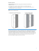
Product purpose The HP MCS G2 is a supplemental cooling system for the data center that offers two configuration options: Preconfigured with a single HP 10000 G2 Series IT rack enclosure (figure 2A) Configured to support two HP 10000 G2 Series IT rack enclosures (the second IT rack is a field-installed option, as shown in figure 2B) Figure 2: HP MCS G2 configuration options The HP MCS G2 integrates with a facility’s chilled water plant or a dedicated chilled water loop to provide dedicated cooling of
Key HP MCS G2 components The HP MCS G2 comprises the key components described below (and shown in figure 3) that work together to provide cooling performance: Main breakers—circuit breakers powering the HP MCS G2 (the breakers don’t control power at the input panel at the rear of the unit) Heat exchanger module—the air-to-water heat transfer device was specially created for demanding data center environments, and is the key component of the HP MCS G2 Display—provides general cooling unit status Mana
HP MCS G2 specifications Physical specifications Table 2 lists the physical specifications of a single HP MCS G2 and server cabinet as received from the factory. Table 2: HP MCS G2 physical specifications (single rack configuration) Parameter Packaged system (as shipped on pallet) Unpackaged system (off pallet, unwrapped) Unpackaged CTO system Height 2,280 mm (89.85 in.) 2,017 mm (79.4 in.) 2,017 mm (79.4 in.) Width 1,219 mm (48 in.) 909 mm (35.8 in.) 909 mm (35.8 in.) Depth 1,829 mm (72 in.
Chapter 2: Facility planning for HP MCS G2 implementation Overview The HP MCS G2 offers an incremental data center cooling solution that is capable of cooling 35 kW of heat from one IT rack or two IT racks. The two basic ways to deploy the HP MCS G2 are as a standalone unit or to place it in a row adjacent to other HP MCS G2 units or standard equipment racks. An approach to water supply and design should take into consideration short- and long-term needs for cooling.
Space and positioning considerations The HP MCS G2 is larger (and, when fully populated, heavier) than a standard 19-inch equipment rack. Therefore, space required for maneuvering, operating, and servicing the HP MCS G2 is greater than for standard-sized racks. Delivery space requirements It is important to ensure the facility has adequate space to receive and remove the HP MCS G2 unit from the shipping skid.
Figure 4 shows the maneuvering space required when unloading the HP MCS G2 (in a single IT rack configuration) from a pallet. Use the delivery forms provided in appendix A when planning for unit maneuvering. Figure 4: HP MCS G2 shipping package delivery and maneuvering space requirements for a single IT rack configuration Caution: It is recommended that a ramp angle of no greater than 5° be used to move the HP MCS cabinet up or down elevations. Typical data center ramps have a 5º angle (1 to 12 pitches).
Figure 5 shows the maneuvering space required when unloading an expansion rack for the HP MCS G2.
Operational space requirements The HP MCS G2 unit is wider and deeper than conventional HP racks to provide for internal airflow and housing of the modular cooling unit components. The recommended minimum amount of access space for the HP MCS G2 in the standard single rack configuration is 1,219 mm (4 feet) in the front and 914 mm (3 feet) in the rear, as shown in figure 6. Figure 6: HP MCS G2 single rack operational space dimensions Note: With the top shipping bracket, the total height is 2,069 mm (81.
An HP MCS G2 installed in a dual rack configuration requires approximately an additional 600 mm of width space to accommodate the second IT rack mounted to the left of the cooling unit, as shown in figure 7.
An HP MCS G2 can also be installed with the HP 10000 series racks 42U 200 mm rear extension kit, as shown in figure 8. The HP 10000 series racks 42U 200 mm rear extension kit provides more space in the rear of the rack for cabling and power distribution equipment. Figure 8: HP MCS G2 with the optional HP 10000 series rack 42U 200 mm rear extension kit Note: With the top shipping bracket, the total height is 2,069 mm (81.5 inches).
System positioning The HP MCS G2 can be installed next to an existing or new row of HP 10000 Series racks. Based on facility design requirements, the cabinets can be arranged in a flush front (figure 9A) or flush rear (figure 9B) configuration.
Cabinet leveling feet The HP MCS G2 system includes leveling feet and does not require fastening to the floor. Care should be taken during the loading of the equipment to ensure the enclosure remains stable during operation and servicing to avoid personnel and equipment damage. Note: The HP MCS G2 unit supports 1,360 kg (3,000 lb) of static loads of IT equipment on the leveling feet. Warning: Static loading limits cannot be achieved if the rack is: 1. Not on its leveling feet, or 2.
Figure 10: Cabinet leveling feet locations (top view of single rack configuration) Figure 11: Cabinet leveling feet and plumbing locations (top view of expansion [dual] rack configuration) 17
Floor loading considerations The computer room floor must be able to support the total weight of the installed server as well as the weight of the HP MCS as they are moved into position. The information presented in this section is about raised floor installations. Note: HP cannot assume responsibility for determining the suitability of a particular raised floor system. The customer or local agencies should determine installation requirements.
Table 5 lists the common floor-loading terms. Table 5: Common floor-loading terms Term Description Dead load The weight of the raised panel floor system, including the understructure; expressed in kg/m2 (lb/ft2) Uniform load The load that the floor system can safely support; expressed in kg/m2 (lb/ft2 or kN/m2) Concentrated load The load that a floor panel can support on a 25 x 25 mm2 (1 x 1 in.
Note: The power requirements discussed in this guide are for the fans and electronics of the HP MCS G2 only. Data processing components such as servers, storage, and network devices must be considered separately based on their individual power requirements. System grounding HP server systems require two methods of grounding: power distribution grounding for safety, and high-frequency signal grounding for equipment performance.
Voltage fluctuations and outages The HP MCS G2 is designed to provide immunity to power outages of less than one cycle. However, testing cannot conclusively rule out loss of service. Therefore, adherence to the following guidelines provides the best possible performance of power distribution systems for HP equipment: Dedicated power source—isolates the power distribution system from other circuits in the facility.
Figure 13: HP MCS power cords NEMA L6-20-to-C19 power cord IEC 309-to-C19 power cord At least one power cord must be used for operation of the HP MCS G2. The second cord can be connected to a redundant AC power bus to improve system availability. In this case, the transfer switch assembly of the HP MCS G2 provides switchover to the active power bus in the event of power source failures or accidentally tripped circuit breakers. Note The power cords are 4.5 meters (14.7 feet) long.
When redundant AC power is available, the redundant AC power cord is connected to the right C20 receptacle, as shown in figure 15.
HP recommends that the water source for the HP MCS G2 be a dedicated chiller unit or water-to-water heat exchanger that allows for line isolation, better control of individual systems, and regulated water quality. The chilled water source for this loop would be provided by one or more chiller systems.
Availability and access to a data center leak detection system to monitor the infrastructure system for leaks Water shutoff and bypass valves to allow infrastructure system flushing for the inlet and outlet of each HP MCS G2 (highly recommended) Air vents installed at the highest point in the pipe system (each HP MCS G2 has an air vent, but additional vents in the supply piping system should be considered) HP recommends the HP Water Hook-up Option Kit AF089A (available at www.hp.
The HP MCS G2 provides two capped T-fittings that allow the main coolant hoses to be routed either through the back of the cabinet and above the floor as shown in figure 19A, or down through the cutouts in a raised floor (recommended) as shown in figure 19B. The right (blue) hose designates the chilled water supplied to the HP MCS G2, and the left (red) hose is the warm water exiting from the HP MCS G2.
Piping approaches HP recommends the following methods for facility plumbing orientation with the HP MCS G2: Direct rear approach Left rear approach Right rear approach Note: It is possible to approach the HP MCS G2 from the front with piping. However, this approach requires careful planning for accessible component locations and hose attachments. Figure 20 shows the recommended facility piping approaches to the HP MCS G2.
Raised floor panels vary in size globally, but all create virtual grid lines or seams where panels come together. These seams are ideal for positioning computer racks on the raised floor. Figures 21–24 reference the location of rack attributes aligned with raised floor seams to provide critical dimensions for floor cutouts. Figure 21: Single rack recommended floor cutouts—option 1 Floor cutout dimensions Item Dimension Item Dimension A 191 mm (7.50 in.) F 150 mm (6.00 in.) B 76 mm (3.00 in.
Figure 22: Single rack recommended floor cutouts—option 2 Floor cutout dimensions Item Dimension Item Dimension A 191 mm (7.50 in.) G 57 mm (2.25 in.) B 76 mm (3.00 in.) H 114 mm (4.50 in.) C 51 mm (2.00 in.) K 114 mm (4.50 in.) F 150 mm (6.00 in.) – – Note: The allowable tolerances are +/– 3.2 mm (+/– 0.125 inches). Due to these tolerances, more attention must be paid to planning the cutouts when installing a row of HP MCS G2 units.
Figure 23: Expansion (dual) rack recommended floor cutouts—option 1 Floor cutout dimensions Item Dimension Item Dimension A 165 mm (7.50 in.) F 150 mm (6.00 in.) B 150 mm (3.00 in.) G 57 mm (2.25 in.) C 64 mm (2.25 in.) J 610 mm (24.00 in.) E 230 mm (9.00 in.) K 114 mm (4.50 in.) Note: The allowable tolerances are +/– 3.2 mm (+/– 0.125 inches). Due to these tolerances, more attention must be paid to planning the cutouts when installing a row of HP MCS G2 units.
Figure 24: Expansion (dual) rack recommended floor cutouts—option 2 Floor cutout dimensions Item Dimension Item Dimension A 191 mm (7.50 in.) F 150 mm (6.00 in.) B 76 mm (3.00 in.) G 57 mm (2.25 in.) C 51 mm (2.25 in.) J 610 mm (24.00 in.) E 230 mm (9.00 in.) K 114 mm (4.50 in.) Note: The allowable tolerances are +/– 3.2 mm (+/– 0.125 inches). Due to these tolerances, more attention must be paid to planning the cutouts when installing a row of HP MCS G2 units.
Chilled water system components The chilled water supply and return service for each HP MCS G2 are required to have a particular combination of components for peak performance. These components are identified in figure 25 and described in table 7. Figure 25: Recommended plumbing configuration for the HP MCS G2 The 1-micron filter may require a minimum clearance of 762 mm (30 inches) under the floor for installation.
Table 7: Typical plumbing components for an HP MCS G2 configuration (refer to figure 26) Item Description Specifications 1 Chilled water return line Pipe: 1-inch, ASTM B88, type L, hard-drawn copper Fittings: ASTM B16.
Item Description Specifications plumbing contractor, typical 1 14 Hose barb Type: ½-inch I.D. hose barb x ¾-inch male NPT, Parker Hannifin, 125HBL-8-12 fitting, or equivalent, installed by plumbing contractor, typical 1 15 Hose Type: 8 mm outer-diameter flexible hose supplied with the HP MCS G2 16 Hose Type: 9 mm inner diameter flexible hose supplied with the HP MCS G2 17 Filter A 1-micrometer filter is recommended for optimal long-term performance of the HP MCS G2.
Note: The HP Water Hook-Up Kit (P/N AF089A) is recommended and should be ordered for each HP MCS G2 to be installed. Coolant requirements General thermal requirements Table 8 lists the coolant requirements that the facility must meet in order to support an HP MCS G2 installation. Table 8: Facility coolant requirements Parameter Value Chilled water temperature6 Minimum Maximum 7°C (45°F) 15°C (59°F) Chilled water flow rate (maximum)7 Approximately 60 lpm (15.
There are several simple steps to determining the coolant requirements and corresponding resources necessary for effective implementation of the HP MCS G2. The flowchart in figure 26 outlines the steps and necessary information and resources for each aspect of the implementation. Figure 26: Coolant implementation flow chart for one rack Cooling loop sizing Sizing the cooling loops can be straightforward based on the planned cooling requirements of each populated/planned HP MCS G2 server enclosure.
Table 9: Rack cooling loop sizing chart Installed component Quantity Maximum watts generated Maximum CFM required Maximum watts total Maximum CFM total Component 1: Component 2: Component 3: Component 4: Component 5: Component 6: Component 7: Component 8: Component 9: Component 10: Total for Cabinet11 After calculating the total expected required heat load, use the charts in the following section titled ―Determining heat load capacities‖ to determine required water flow and pressure based on potentia
Table 11: Minimum heat load at different water supply and server air intake temperatures Server air intake temperature 20°C (68ºF) 25°C (77ºF) Water supply temperature Minimum heat load 7.5°C (45.5ºF) 8 kW 10°C (50ºF) 7 kW 12.5°C (54.5ºF) 5 kW 15°C (59ºF) 4 kW 7.5°C (45.5ºF) 12 kW 10°C (50ºF) 9 kW 12.5°C (54.5ºF) 7 kW 15°C (59ºF) 6 kW Note: Not providing the minimum heat load can cause unstable control of the temperatures and flow rates of the HP MCS G2.
Figure 27: HP MCS G2 coolant flow requirements with 20°C (68°F) server intake air Figure 28: HP MCS G2 coolant flow requirements with 25°C (77°F) server intake air 39
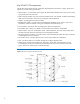
The pressure drop chart in figure 29 is provided as a reference to indicate water flow vs. the water pressure for a fully opened HP MCS G2 water control valve. Figure 29: Flow rate vs. delta pressure (water control valve fully open) Note: A minimum water pressure difference of 14.5 psi (1.0 bar) between facility supply and return is required. Figure 30 gives the pressure difference with a fully opened control valve.
Water quality requirements Closed-loop water must not contain any lime scale deposits or loose debris. The water should have a low level of hardness, particularly a low level of carbon hardness. Filters should be used to remove free-floating particulates and be regularly maintained. Additionally, the water should not be so soft that it attacks the materials with which it comes into contact. It is necessary to periodically add new fresh water, but also to remove some of the enriched water.
Another consideration for water is the required set point. Temperatures near or below 0°C (32°F) mean that the chilled water plant condenser is very close to or below the freezing point of the water (remember, the minimum chilled water temperature to be supplied to the HP MCS G2 is 7°C/45°F). This could cause a blockage and damage to the unit, so an additive like glycol may be necessary to lower the freezing point.
Environmental considerations Table 13 lists the recommended environmental specifications for the HP MCS G2. Table 13: Recommended environmental specifications Parameter Value Room temperature (see note) Recommended minimum/maximum 20°C (68°F)/25°C (77° F) Allowable minimum/maximum 15°C (59°F)/32°C (90° F) Humidity: Recommended range 40%–50% Allowable range 20%–60% Note The temperatures stated are for an elevation of 0 to 5,000 feet above sea level.
Appendix A: forms and checklists Delivery survey form The delivery survey form (figure 30) lists delivery or installation requirements. If any of the items on the list apply, enter the appropriate information in the areas provided on the form. Special instructions or recommendations should be entered on the special instructions or recommendations form.
Pre-installation checklists Site preparation checklist Table 14 is a site preparation checklist. For each item, please check ―yes‖ or ―no‖ in the appropriate column. If answering ―no,‖ include a comment and the date. A ―no‖ answer means that an alternative may be required.
Item Area/ condition Cooling considerations 24 Can the room temperature be maintained between the recommended range of 20°C to 25°C (68°F to 77°F) and allowable range of 15°C to 32°C (59°F to 90°F) (up to 5,000 ft)? Derate 1°C/1,000 ft above 5,000 ft and up to 10,000 ft.
Appendix B: conversion factors and formulas The conversion factors provided in this appendix are intended to ease data calculation for systems that do not provide information in the format requested in this site preparation guide. The following list includes the conversion factors used in this document, as well as additional conversion factors that might be helpful in determining those factors required for site planning. Conversion factors for refrigeration 1 watt = 0.86 kcal/hour 1 watt = 3.
Appendix C: glossary Table 15 lists technical terms and abbreviations used in this guide.
Term Description True power In an AC circuit, true power is the actual power consumed and is measured in watts. It is distinguished from apparent power by eliminating the reactive power component that may be present. Typical input current The operating current of the product measured using a typical load and target voltage Typical power consumption Represents the expected power consumption of a given configuration.