
HP Modular Cooling System Generation 2 site preparation guide - Technical white paper


26
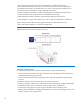
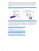
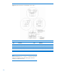
The HP MCS G2 provides two capped T-fittings that allow the main coolant hoses to be routed either
through the back of the cabinet and above the floor as shown in figure 19A, or down through the
cutouts in a raised floor (recommended) as shown in figure 19B. The right (blue) hose designates the
chilled water supplied to the HP MCS G2, and the left (red) hose is the warm water exiting from the
HP MCS G2.
Figure 19: Main coolant line hookup options for the HP MCS G2
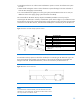
The HP MCS G2 also includes condensate and overflow tubing. Each tube is approximately 3 meters
(9 feet) in length. The overflow hose has an inner diameter of 9 mm, and the condensation hose has
an outer diameter of 8 mm. The preferred method of routing for all hoses is downward, without loops,
and away from the HP MCS G2 cabinet. Pumped condensation and gravity-fed overflow hoses
should be routed to a reclaim system.
Note:
Flexible attachment hoses are intended to allow for deflection in any
direction for equipment mounted on dynamic platforms, or for slight
relocation of cabinets.
Note:
Installation service for the MCS G2 is order number UE005E.