
HP Modular Cooling System Generation 2 site preparation guide - Technical white paper


27
Piping approaches
HP recommends the following methods for facility plumbing orientation with the HP MCS G2:
Direct rear approach
Left rear approach
Right rear approach
Note:
It is possible to approach the HP MCS G2 from the front with piping.
However, this approach requires careful planning for accessible component
locations and hose attachments.
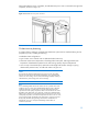
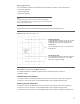
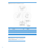
Figure 20 shows the recommended facility piping approaches to the HP MCS G2.
Figure 20: Piping locations for the HP MCS G2
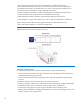
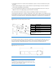
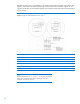
Raised floor cutouts for HP MCS G2 hoses
A complete HP MCS G2 installation typically requires the following floor cutouts in a
raised-floor facility:
Standard (single) rack configuration:
One floor cutout for the chilled water hoses, drain hoses, and power cords of the cooling unit
One floor cutout for the power cords and data cables of the computer equipment rack
Expansion (dual) rack configuration:
One floor cutout for the chilled water hoses, drain hoses, and power cords of the cooling unit
One floor cutout for the power cords and data cables of the computer equipment rack
One floor cutout for the power cords and data cables of the expansion computer equipment rack
Alternate piping location
Locating chilled water piping taps in front of the HP MCS
G2 (under the floor) is possible. This option requires
careful planning due to the MCS chilled water hose
length limitation.
Preferred piping location
Locate chilled water piping taps behind the HP MCS G2
either under the floor or above the floor. The chilled
water taps must approach laterally.
Do not locate piping connections or components under
the HP MCS G2.