
HP Modular Cooling System Generation 2 site preparation guide - Technical white paper


28
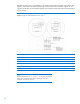
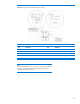
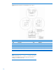
Raised floor panels vary in size globally, but all create virtual grid lines or seams where panels come
together. These seams are ideal for positioning computer racks on the raised floor. Figures 21–24
reference the location of rack attributes aligned with raised floor seams to provide critical dimensions
for floor cutouts.
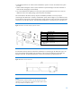
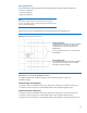
Figure 21: Single rack recommended floor cutouts—option 1
Floor cutout dimensions
Item
Dimension
Item
Dimension
A
191 mm (7.50 in.)
F
150 mm (6.00 in.)
B
76 mm (3.00 in.)
G
57 mm (2.25 in.)
C
57 mm (2.25 in.)
K
114 mm (4.50 in.)
E
230 mm (9.00 in.)
–
–
Note:
The allowable tolerances are +/– 3.2 mm (+/– 0.125 inches). Due to these
tolerances, more attention must be paid to planning the cutouts when
installing a row of HP MCS G2 units.