
HP Modular Cooling System Generation 2 site preparation guide - Technical white paper


35
Note:
The HP Water Hook-Up Kit (P/N AF089A) is recommended and should be
ordered for each HP MCS G2 to be installed.
Coolant requirements
General thermal requirements
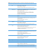
Table 8 lists the coolant requirements that the facility must meet in order to support an HP MCS G2
installation.
Table 8: Facility coolant requirements
Parameter
Value
Chilled water temperature
6
Minimum
Maximum
7°C (45°F)
15°C (59°F)
Chilled water flow rate (maximum)
7
Approximately 60 lpm (15.8 gpm)
Inlet/outlet water connections to HP MCS G2 (quantity 2)
8
1-inch BSPP (parallel-thread)
Hose/coupler insulation thickness
6.3 mm (0.25 in.) minimum, closed cell
Condensate discharge tubing
3 m (118 in.) length
8 mm (0.31 in.) outer diameter
6 mm (0.24 in.) inner diameter
Overflow tubing
3 m (118 in.) length
15 mm (0.59 in.) outer diameter
9 mm (0.35 in.) inner diameter
Chilled water pressure differential at required flow
Minimum 1 bar required
9
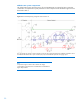
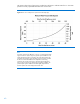
Cooling capacity
10
35 kW maximum
(Performance is affected by water temperature;
see figures 19–21)
In addition to the requirements listed in table 8, the coolant must meet the requirements prescribed in
the section ―Water quality requirements.‖
6, 7, 9, 10
For more information, refer to the section ―Determining heat load capacities.‖
7
8
For more information, refer to the section ―Plumbing considerations.‖
9
10