
HP Modular Cooling System Generation 2 site preparation guide - Technical white paper


36
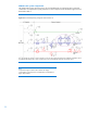
There are several simple steps to determining the coolant requirements and corresponding resources
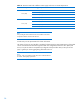
necessary for effective implementation of the HP MCS G2. The flowchart in figure 26 outlines the
steps and necessary information and resources for each aspect of the implementation.
Figure 26: Coolant implementation flow chart for one rack
Cooling loop sizing
Sizing the cooling loops can be straightforward based on the planned cooling requirements of each
populated/planned HP MCS G2 server enclosure. The amount (watts) of heat to be removed from
each component in the server rack should be added together to calculate the total heat to be removed
by the HP MCS G2 cabinet. Table 9 may be copied for documenting individual cabinet calculations.
Calculations should include the equipment installed today and additional equipment planned for
installation over the design life of the system.