
HP Modular Cooling System Generation 2 site preparation guide - Technical white paper


37
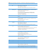
Table 9: Rack cooling loop sizing chart
Installed
component
Quantity
Maximum watts
generated
Maximum CFM
required
Maximum watts
total
Maximum CFM
total
Component 1:
Component 2:
Component 3:
Component 4:
Component 5:
Component 6:
Component 7:
Component 8:
Component 9:
Component 10:
Total for Cabinet
11
After calculating the total expected required heat load, use the charts in the following section titled
―Determining heat load capacities‖ to determine required water flow and pressure based on potential
chilled water temperatures. The pressure should be measured prior to the cold water inlet and after
the warm water outlet. All water system equipment, materials, and installation must comply with any
applicable construction codes and LAHJ.
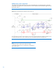
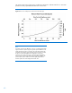
Determining heat load capacities
The total cubic feet per minute (CFM) required by the equipment installed in each server rack must be
compared with the total available supply from the HP MCS G2 so it is not exceeded. The fans in the
HP MCS G2 are controlled in four steps to reduce the airflow when the maximum cooling capacity is
not demanded from the HP MCS G2. Table 10 gives a few examples of the approximate fan steps by
the demanded cooling capacity from the HP MCS G2.
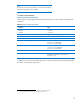
Table 10: Approximate fan step at certain cooling capacity
Fan step
Cooling capacity
2
10 kW
3
20 kW
4
35 kW
Because of the air inlet located on both sides of the fans, the difference in air flow in both racks in a
dual rack configuration is negligible. Also, uneven load in both racks can be supported by the dual
rack configuration without high effects on the server air inlet temperature.
For the proper operation of the HP MCS G2, a minimum heat load in the racks is necessary
depending on the water supply temperature, as shown in table 11.
11
An approximate value can be estimated by assuming all power entering the cabinet is converted to heat.