
HP Modular Cooling System Generation 2 site preparation guide - Technical white paper


40
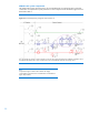
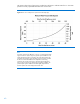
The pressure drop chart in figure 29 is provided as a reference to indicate water flow vs. the water
pressure for a fully opened HP MCS G2 water control valve.
Figure 29: Flow rate vs. delta pressure (water control valve fully open)
Note:
A minimum water pressure difference of 14.5 psi (1.0 bar) between facility
supply and return is required. Figure 30 gives the pressure difference with
a fully opened control valve. In operation, the control valve maintains the
water flow to the HP MCS G2 by introducing pressure resistance to reduce
the flow to accommodate different water temperatures and cooling
capacities. This way the pressure loss in operation appears higher than
shown in figure 30. But to have the full scale of water flow available, the
provided system pressure difference should be slightly higher than the
maximum pressure loss with a fully opened control valve.