HP Modular Cooling System Site Preparation Guide
Legal Notices The information in this document is subject to change without notice. Hewlett-Packard makes no warranty of any kind with regard to this manual, including, but not limited to, the implied warranties of merchantability and fitness for a particular purpose. Hewlett-Packard shall not be held liable for errors contained herein or direct, indirect, special, incidental or consequential damages in connection with the furnishing, performance, or use of this material.
Table of Contents Legal Notices ...................................................................................................................................... 2 Restricted Rights Legend.................................................................................................................... 2 Copyright Notices ............................................................................................................................ 2 Table of Contents......................................
Conversion Factors for Refrigeration................................................................................................. 51 Metric Equivalents .......................................................................................................................... 51 kVA Conversions............................................................................................................................ 51 Formulas ..............................................................................
Preface Safety and Regulatory Information For your protection, this product has been tested to various national and international regulations and standards. The scope of this regulatory testing includes electrical/mechanical safety, radio frequency interference, acoustics, and know hazardous materials. Where applicable, approvals obtained from third-party test agencies are shown on the product label.
Safety in Material Handling WARNING: Do not lift the cabinet manually. To avoid physical injury you must use a mechanical lifting device. WARNING: Use care when working with hazardous voltages. This equipment may be configured with dual input line sources. Hazardous voltages and energy maybe present even after the removal of a single input source. Trained service personnel must follow the service guidelines. Be sure to check that the differences in ground sources meet LAHJ.
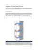
Chapter 1 HP Modular Cooling System Overview This chapter provides an overview of the HP Modular Cooling System. Throughout this chapter, the various specifications and aspects of the system are defined as thoroughly as possible to ensure that all data is considered for a successful site preparation. Product Overview The HP Modular Cooling System (MCS) is a modular, distributed cooling solution that removes the high levels of heat generated by today’s advanced server and mass storage systems.
fully-populated rack of server or other IT equipment. Warmed air is then channeled into the sidemounted MCS unit, cooled, then re-circulated to the front of the server stack. The special horizontal air flow of the HP Modular Cooling System fully supports this widespread cooling principle and distributes cooled air uniformly throughout the complete height of the enclosure (i.e., all devices receive adequate and evenly distributed cool air regardless of their mounting position within the enclosure).
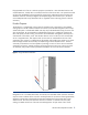
(482.6 mm) mounting space must be used either by equipment or filled with blanking panels. The area on each side of the 19-inch (482.6 mm) rails should also be closed to air flow leakage, so all cool air provided by the Modular Cooling System is routed exclusively "through" the equipment to be cooled and bypass is minimized. Figure 3.
Key HP MCS Components The HP MCS is comprised of the key components described below (and shown in Figure 4) that work together to provide cooling performance: • Fan Module—Module containing one of the main, internal circulation fans. There are three fan modules within the HP Modular Cooling System. • Heat Exchanger Module (HEX)—The air-to-water heat transfer device was specially-created for demanding data center environments, and is the key component within the heat exchanger unit.
HP MCS Specifications Physical Specifications Table 2 lists the physical specifications of a single HP MCS and server cabinet as received from the factory. Table 2. HP MCS Physical Specifications Parameter Packaged system (as shipped on pallet) Unpackaged system (off pallet, unwrapped) Unpackaged CTO system Height 88.5 in. (2248 mm) 78.7 in (1999 mm) 78.7 in. (1999 mm) Width 48 in. (1219 mm) 35.8 in. (909 mm) 35.8 in. (909 mm) Depth 70 in. (1778 mm) 51 in. (1295 mm) 51 in.
Chapter 2 Facility Planning for HP MCS Implementation Overview The HP Modular Cooling System offers an incremental data center cooling solution, capable of cooling 35 kW of heat per MCS cabinet. The two basic ways to deploy the HP MCS are as a stand-alone unit or placed in a row adjacent to other HP MCS units or standard equipments racks. An approach to water supply and design should take into consideration short- and long-term need for cooling.
Space Considerations The HP MCS is larger (and, when fully populated, heavier) than a standard 19-inch equipment rack. Space for maneuvering, operating, and servicing the HP MCS are therefore greater than standard-sized racks. Delivery and Maneuvering Space Requirements It is important to ensure the facility has adequate space to receive and remove the HP MCS unit from the shipping skid.
Figure 5. HP MCS Shipping Package Delivery and Maneuvering Space Requirements 70” (1778 mm) 103” (2616.2 CAUTION: It is recommended that a ramp angle of no greater than 5° be used to move the HP MCS cabinet up or down elevations. 228”/19’ (5.
Operational Space Requirements The HP MCS unit is wider and deeper (Figure 6) than conventional HP racks to provide for internal airflow and housing of the modular cooling unit components. The recommended minimum amount of access space for an installed HP MCS is 4 feet (1219 mm) in the front and 3 feet (914 mm) in the rear. Figure 6. HP MCS dimensions (approximate) (Top View) 36” (914mm) 48” (1279mm) The HP Modular Cooling System with server rack requires considerations such as weight and aisle spacing.
Figure 7 provides the detailed MCS dimensions, while Figure 24 gives detailed dimensions of leveling foot placement. Figure 7. Detailed Cabinet Dimensions (Top View) General location of floor opening. Refer to Chapter 3, "HP MCS Installation Guidelines" for detailed cutout Information. 51” (1295 mm) NOTE: The HP MCS includes leveling feet and rear casters that swivel.
In advance of cabinet placement, a cutout of 6.25 inches (159 mm) width x 6 inches (150 mm) depth will be required for water hose access near the left rear of the cabinet. Please ensure there is adequate floor remaining, and supporting understructure, to support the load-bearing leveling feet, especially immediately around the cutout. Once the HP MCS is positioned in the proper location in data center, it can be lowered into place with the leveling feet.
Floor Loading The computer room floor must be able to support the total weight of the installed server as well as the weight of the HP MCS as they are moved into position. The information presented in this section is directed toward raised floor installations. NOTE: HP cannot assume responsibility for determining the suitability of a particular raised floor system. The customer or local agencies should determine installation requirements.
Table 5 lists the common floor loading terms. Table 5. Common Floor Loading Terms Term Description Dead load The weight of the raised panel floor system, including the understructure. Expressed in lb/ft2 (kg/m2). Uniform load The load that the floor system can safely support. Expressed in lb/ft2 (kg/m2).
Electrical Considerations The HP MCS provides two C20-type AC input connections and ships with two sets of power cords for connecting to redundant AC power busses, if available. Only one power cord is necessary for operation. The second cord can be connected to a redundant AC power bus to improve system availability by protecting against power source failures or accidentally tripped circuit breakers. NOTE; Electrical practices and suggestions in this guide are based on North American practices.
Each floor panel should have at least one supporting pedestal grounded to the power panel and another pedestal grounded to an equipment cabinet. This broadband solution provides excellent grounding for maximum safety and performance. Figure 9. Raised Floor Grounding Voltage Fluctuations and Outages The HP Modular Cooling System is designed to provide immunity to power outages of less than one cycle. However, testing cannot conclusively rule out loss of service.
Coolant Source Planning A number of factors relating to a chilled water distribution system must be considered during the site preparation process, including the following: • Type of water source: shared water or dedicated chilled water loop • Maximum and minimum temperatures of building chilled water plant, and target chilled water temperature of dedicated loop based on total cooling capacity required and planned • Viscosity of the chilled liquid, combined with the length and elevation changes in piping de
Figure 10.
The HP MCS is provided with 1-¼-inch diameter flexible inlet and outlet chilled water hoses, each with an overall length of approximately 44 inches (1100 mm) and consisting of about 34 inches (864 mm) of flexible hose terminated at each end with fittings (Figure 11). Figure 11. HP MCS Outlet Water Hose. CAUTION: It is essential that the proper cabinet and facility cool water inlet and warm water outlet hoses are connected properly. A check valve prevents reverse flow.
The HP MCS also includes condensate and overflow tubing. Each tube is approximately 9 feet (3 meters) in length. The overflow hose has an outer diameter of 14 mm and an inner diameter of 9.5 mm. The condensation has an outer diameter of 6 mm and an inner diameter of 4 mm. The preferred method of routing for all hoses is downward, without loops, and away from the MCS cabinet. Pumped condensation and gravity-fed overflow hoses should be routed to a reclaim system.
Figure 14. Recommended Plumbing Configuration for the HP MCS.
Table 7. Plumbing Components for a HP MCS Configuration (Ref. Figure 14) Item Description Specifications 1 Chilled Water Return Line Pipe: 1 ¼-inch copper, Type L, hard-drawn Fittings: Wrought copper Solder: 95-5 Tin Antimony Thread Sealant: RectorSeal® No. 7, RectorSeal® Tru-Blu™, or equivalent Preparation: Cut tubing square and remove burrs. Clean both inside of fittings and outside of tubing with steel wool and muriatic acid before sweating.
Item Description Specifications 8 System Drain Valve Type: ¾-inch two-piece, full-port, brass ball valve with chrome plated brass ball, PTFE seats, steel handle, with solder end connections. Pressure rating: 600psi WOG, 150psi WSP. Centerline elevation: 6 inches minimum above base floor. Orientation: Stem vertical up for lateral level operation. Watts® FBVS-3C or equivalent, typical 1 9 Hose Adapter Type: ¾-inch brass hose thread adapter, typical 1.
• HP MCS condensate and overflow hoses do not require insulation. • Filters may require a minimum of 30 inches (762 mm) clearance under the floor for installation. If the filters cannot be installed under the floor due to space constraints, they may be placed upstream of the piping system. A pre-installed quick release coupling is provided on each of the cabinet inlet and outlet hoses. The mating coupling will need to be installed to each of the chilled water and return lines.
Coolant Requirements Table 8 lists the coolant requirements that the facility must meet to support an HP MCS installation. Table 8. Facility Coolant Requirements Parameter Chilled Water Temperature [1] Minimum Maximum Chilled Water Flow Rate (maximum) [1] Inlet/Outlet Water Connections to HP MCS [2] Hose/Coupler insulation thickness Condensate Discharge Tubing Overflow Tubing Chilled Water Pressure Differential At Required Flow Cooling Capacity [1] Value 41° F (5° C) Min.
There are several simple steps to determining the coolant requirements and corresponding resources necessary for effective implementation of the HP MCS. The flowchart in Figure 15 outlines the steps and necessary information/resources for each aspect of the implementation. Figure 15. Coolant Implementation Flow Chart Determine Maximum Server Heat Load & Desired Intake Temperature for The Rack (e.g., 16 kW/25° C) Refer to the table in the section titled “Coolant Loop Sizing.
Table 9. Cabinet Cooling Calculation Chart Installed Component Qty Max. Watts Generated Max. CFM Required Max. Watts Total Max. CFM Total Component 1: Component 2: Component 3: Component 4: Component 5: Component 6: Component 7: Component 8: Component 9: Component 10: Total for Cabinet [1] NOTES: [1] An approximate value can be estimated by assuming all power entering the cabinet is converted to heat.
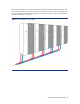
Figure 16. HP MCS Coolant Flow Requirements with 20° C Server Intake air 35 5º C water Server Heat (kW) 30 25 10º C 20 water 15 15º C water 10 5 0 5 (19) 10 (38) 15 (57) 20 (76) Flow Rate gpm (lpm) 25 (95) Figure 17.
The following pressure drop chart offers a guide to calculate the relationship between pressure drop and flow rate for liquid cooling water supply source calculations. Figure 18.
Water Quality Requirements Closed-loop water must not contain any lime scale deposits or loose debris. The water should have a low level of hardness, particularly a low level of carbon hardness. Filters should be used to remove free floating particulates and regularly maintained. Additionally, the water should not be so soft that it attacks the materials with which it comes into contact. It is necessary to periodically add new fresh water, but also to remove some of the enriched water.
Another consideration for water is the required set point. Temperatures near or below 32°F (0°C) mean the chilled water plant condenser is very close to or below the freezing point of the water (remember, the minimum chilled water temperature to be supplied to the MCS is 41oF/5oC).
Environmental Considerations Table 11 lists the recommended environmental specifications for the HP MCS. Table 11. Recommended Environmental Specifications Parameter Room Temperature (see note) Recommended Minimum / Maximum Allowable Minimum / Maximum Humidity: Recommended range Allowable range Value 68° F (20° C) / 77° F (25° C) 59° F (15° C) / 90° F (32° C) 40% - 50% 20% - 60% NOTE: The temperatures stated are for an elevation of 0 to 5,000 feet above sea level.
Chapter 3 HP MCS Installation Guidelines Introduction This chapter describes basic methods and provisions for installing the HP MCS. For more information on installing the HP MCS refer to the HP MCS Installation Overview (document part number 399330-001), downloadable from www.hp.com. System Positioning The HP MCS can be installed next to an existing or new row of HP 1000 Series racks.
NOTE: Be aware of the potential for slight front or rear door swing interference when arranging the HP MCS immediately next to a HP 10000 Series rack, depending on the configuration. Equipment may require the removal of a door for full, unimpeded access. Piping Approaches There are many different ways to approach the HP MCS with chilled water piping. Note, however, that facility pipes must end within a critical distance of the HP MCS for accessible connections.
Figure 20.
Figure 21.
Figure 22.
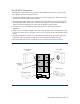
Raised Floor Cutouts for MCS Hoses A complete HP MCS typically requires two floor cutouts: • One cutout for the HP MCS rack chilled water hoses, drain hoses, and power cords • One cutout for the computer equipment rack power cords and data cables Raised floor panels vary in size globally, but all create virtual grid lines or seams where panels come together. These seams are ideal for positioning computer racks on the raised floor.
Figure 24. Recommended Floor cutouts – Option 2 MCS Rack Cutout Dimensions Item Dimension A 6.25 in (165 mm) B 6.00 in (150 mm) D 3.00 in (76 mm) Computer Equipment Rack Cutout Dimensions Item Dimension F 6.00 in. (150 mm) G 2.25 in. (57mm) H 4.50 in. (115 mm) NOTE: Allowable tolerance: +/– 0.125 in (+/– 3.
Control System The HP MCS includes a control system that constantly monitors the HP MCS air temperatures, water temperatures, and flow rate. If the air temperature falls below a target setpoint, the HP MCS management module will adjust the fan speed and or flow rate to maintain the setpoint temperature. If the set point temperature cannot be maintained, the HP MCS management module will generate an alarm and notify facility management systems as configured.
When using only a single (primary) source for power, the power cord is connected to the left-most C20 receptacle (when viewed from the rear of the cabinet) as shown in Figure 26. Figure 26. Single-source AC power connection When redundant AC power is available, the redundant power cord is connected to the right C20 receptacle as shown in Figure 27. Figure 27.
Before Installing/Running Active Components… Prior to starting up any active components (servers, storage devices, etc.) mounted in the HP MCS rack unit, the following steps must be performed. • Ensure that the chilled water source is on and flowing prior to the start-up of an HP MCS unit. • Make sure the HP MCS is fully operational and running before turning on the servers and closing the front/rear cabinet doors.
Appendix A Forms and Checklists Delivery Survey Form The delivery survey form (Figure 28) lists delivery or installation requirements. If any of the items on the list apply, enter the appropriate information in the areas provided on the form. Special instructions or recommendations should be entered on the special instructions or recommendations form.
Pre-Installation Checklists Site Preparation Checklist Table 12 is a site preparation checklist. For each item, please check yes or no in the appropriate column. If answering “No,” include a comment and the date. A “No” answer means that an alternative may be required.
Item Area/ Condition Yes 18 Is the dedicated branch circuit less than 75 feet (22.
Appendix B Conversion Factors and Formulas The conversion factors provided in this appendix are intended to ease data calculation for systems that do not provide information in the format requested in this Site Preparation Guide. The following list includes the conversion factors used in this document, as well as additional conversion factors that might be helpful in determining those factors required for site planning. Conversion Factors for Refrigeration • 1 watt = 0.86 kcal/hour • 1 watt = 3.
Appendix C Glossary Table 13 lists technical terms and abbreviations used in this guide. Table 13 Terms and Abbreviations Term Description Apparent power A value of power for AC circuits that is calculated as the product of RMS current times RMS voltage, without taking the power factor into account. ASL Above sea level BTU/hr British Thermal Units per hour. The amount of heat required to raise one pound of water 1° F/hr, a common measure of heat transfer rate.
Term Description True power In an AC circuit, true power is the actual power consumed and is measured in watts. It is distinguished from apparent power by eliminating the reactive power component that may be present Typical input current The operating current of the product measured using a typical load and target voltage. Typical power consumption Represents the expected power consumption of a given configuration.