
HP Modular Cooling System Site Preparation Guide

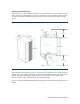
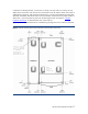

In advance of cabinet placement, a cutout of 6.25 inches (159 mm) width x 6 inches (150 mm)
depth will be required for water hose access near the left rear of the cabinet. Please ensure there is
adequate floor remaining, and supporting understructure, to support the load-bearing leveling feet,
especially immediately around the cutout. Once the HP MCS is positioned in the proper location in
data center, it can be lowered into place with the leveling feet. Refer to Chapter 3 “
HP MCS
Installation Guidelines” for detailed water hose cutout locations.
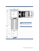
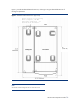
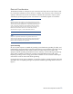
Figure 8 provides the detailed locations of load-bearing leveling feet to assist with floor placement.
Figure 8. Cabinet Leveling Foot Positions & Floor Cutout Location (Top View)
General location
of floor opening.
Refer to Chapter
3, "HP MCS
Installation
Guidelines" for
detailed cutout
This
leveling
foot
remains up
HP MCS Site Preparation Guide
17