
HP Modular Cooling System Site Preparation Guide

The HP MCS also includes condensate and overflow tubing. Each tube is approximately 9 feet (3
meters) in length. The overflow hose has an outer diameter of 14 mm and an inner diameter of 9.5
mm. The condensation has an outer diameter of 6 mm and an inner diameter of 4 mm. The
preferred method of routing for all hoses is downward, without loops, and away from the MCS
cabinet. Pumped condensation and gravity-fed overflow hoses should be routed to a reclaim
system.
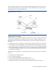
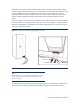
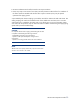
As shown in Figure 13, the main water, condensate, and overflow hoses can be routed through the
back of the cabinet, or down (preferred) through the cutouts in the raised floor. The right (shown in
blue) hose is designated for chilled water into the MCS, and the left (shown in red) hose for warm
water out of the HP MCS cabinet.
Figure 13. Coolant lines Entering and Exiting the HP MCS.
Main outlet
Condensation line
Overflow line
Main inlet
NOTE:
Flexible attachment hoses are intended to allow for deflection in any
direction for equipment mounted on dynamic platforms, or for slight
relocation of cabinets.
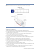
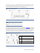
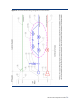
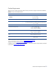
The chilled water taps supplying each HP MCS require a particular combination of components for
optimal performance. These components are identified in Figure 14 and described in Table 7.
HP MCS Site Preparation Guide
25