
HP Modular Cooling System Site Preparation Guide

Coolant Requirements
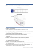
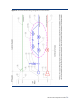
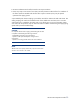
Table 8 lists the coolant requirements that the facility must meet to support an HP MCS installation.
Table 8. Facility Coolant Requirements
Parameter Value
Chilled Water Temperature [1]
Minimum
Maximum
41
° F (5° C) Min.
59
° F (15° C) Max
Chilled Water Flow Rate (maximum) [1] Approximately 20 gpm (76 lpm)
Inlet/Outlet Water Connections to HP MCS [2]
44-in. (1 meter) flexible hose pre-installed on MCS, with 1¼-in.
(31.8 mm) quick disconnect coupling (included) with pipe thread
size 1¼ in. NPTF
Hose/Coupler insulation thickness 0.25-in. min. (6.3 mm), closed cell
Condensate Discharge Tubing
118 in. (3 Meters) length,
0.24 in. (6 mm) outer diameter,
0.16 in. (4 mm) inner diameter
Overflow Tubing
118 in. (3 Meters) length,
0.40 in. (10 mm) outer diameter,
0.28 in. (7 mm) inner diameter
Chilled Water Pressure Differential At Required
Flow
Varies according to flow rate [3]
Cooling Capacity [1]
35 kW Maximum (Performance is affected by water temperature
and flow rate)
NOTES:
[1] For more information, refer to the section titled “
Determining Heat Load Capacities”
[2] For more information, refer to the section titled “
Plumbing considerations”
[3] Refer to section titled “
Determining Heat Load Capacities”
In addition to the requirements listed in Table 8, the coolant must meet the requirements prescribed
in the section “
Water Quality Requirements.”
HP MCS Site Preparation Guide
30