
HP Modular Cooling System Site Preparation Guide
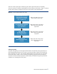
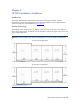

There are several simple steps to determining the coolant requirements and corresponding
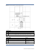
resources necessary for effective implementation of the HP MCS. The flowchart in Figure 15 outlines
the steps and necessary information/resources for each aspect of the implementation.
Figure 15. Coolant Implementation Flow Chart
Determine Maximum Server
Heat Load & Desired Intake
Temperature for The Rack
(e.g., 16 kW/25° C)
Determine Maximum Available
Coolant Temperature
(e.g., 10 C/50° F)
Select Required
Flow Rate From Charts
(e.g., 10 gpm/38 lpm)
Select Required
Water Pressure From Chart
(7.5 psid)
Refer to the table in the section
titled “Coolant Loop Sizing.”
Refer to the charts in the section
titled “Determining Heat Load
Capacities.”
Refer to the charts in the section
titled “Determining Heat Load
Capacities.”
Refer to the chart in the section
titled “Determining Heat Load
Capacities.”
Cooling Loop Sizing
Sizing the cooling loops can be straight forward based on the planned cooling requirements of
each populated/planned MCS server enclosure. The amount (watts) of heat to be removed from
each component in the server rack should be added together for the total heat to be removed by
the HP MCS cabinet. Table 9 may be copied for documenting individual cabinet calculations.
Calculations should include the equipment installed today and additional equipment planned for
installation over the design life of the system.
HP MCS Site Preparation Guide
31