
HP Modular Cooling System Site Preparation Guide
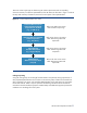
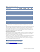
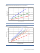
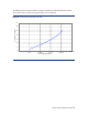
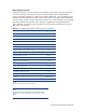
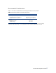
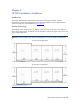
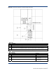

Table 9. Cabinet Cooling Calculation Chart
Installed Component Qty
Max. Watts
Generated
Max. CFM
Required
Max.
Watts
Total
Max.
CFM
Total
Component 1:
Component 2:
Component 3:
Component 4:
Component 5:
Component 6:
Component 7:
Component 8:
Component 9:
Component 10:
Total for Cabinet [1]
NOTES:
[1] An approximate value can be estimated by assuming all power entering the cabinet is converted to
heat.
After calculating the total expected required heat load, use the charts in the following section titled
“Determining Heat Load Capacities” to determine required water flow and pressure based on
potential chilled water temperatures. The pressure (PSID) should be measured prior to the cold
water inlet/after warm water outlet. All water system equipment, materials, and installation must
comply with any applicable construction codes and LAHJ.
Determining Heat Load Capacities
The total CFM required by the equipment installed in each server rack must be compared with the
total available supply from the HP Modular Cooling System (2700 CFM) so it is not exceeded.
Consult with your HP representative for further information.
The charts in Figures 16 and 17 offer a guideline for determining the approximate amount of heat
that can be removed from a HP Modular Cooling System cabinet based on 20° C and 25° C
server intake air temperatures (in degrees Celsius) and flow rates (in gallons per minute (gpm) or
liters per minute (lpm)) being delivered to the unit.
NOTE:
The term “water” in the following charts refers to the coolant suggested
in section titled “
Water Quality Requirements.”
HP MCS Site Preparation Guide
32