
Replacement Instructions for the Operator Display HP Modular Cooling System
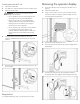

4. Connect the connector between the operator display and
display button.
5. Slide any extra slack in the cable lines up into the operator
display rear cover, and secure by inserting the rubber grommet
into the designated notch on the operator display rear cover.
6. Using an 8 mm socket or wrench, secure the operator display
rear cover to the back of the operator display by inserting three
nuts and external star washers.
7. Complete the operation checklist.
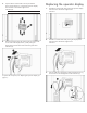
Operation checklist
1. If power was disconnected, restore power to the
MCS unit.
a. Open the rear MCS door.
b. Connect the network cable to the RJ-45 connector on the
power inlet box.
c. Connect the two AC power cables to the power connectors
on the power inlet box.
d. Open the front MCS door.
e. Turn on the AC1 breaker on the AC transfer switch.
f. Turn on the AC2 breaker on the AC transfer switch.
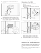
2. Clear all old logs from the web interface to ensure that any
additional alarms are current.
3. Confirm that no additional warning or alarm messages have
been detected by looking at the operator display.
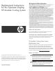
Returning the failed component
Instructions are provided on the return label supplied with the
replacement component. The return label is either in the box in which
the component was shipped or in the plastic pouch attached to the
box.
For further information about the Customer Self Repair program, see
http://www.hp.com/go/selfrepair.