
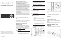
Replacement Instructions for the Water Inlet Coupling HP Modular Cooling System
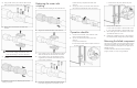


2. Using an Allen wrench, remove the four Allen nuts and
bolts securing the two brackets to the water inlet hose.
3. Remove the two brackets from around the water
inlet hose.
IMPORTANT: Water will drain out of the hose when
you remove the coupling. Be prepared to catch
excess water drainage in a bucket or floor drain.
4. Remove the water inlet coupling from the water
inlet hose.
To replace this component, see "Replacing the water inlet
coupling (on page 2)."
Replacing the water inlet
coupling
1. Insert the water inlet coupling into the water inlet hose.
2. Align the two brackets around the water inlet hose.
3. Using an Allen wrench, insert and tighten three 40-mm
Allen nuts and bolts into three of the four screw holes.
4. Using an Allen wrench, insert and tighten one of the
original Allen nuts and bolts into the remaining screw
hole. Compress completely.
5. One by one, replace the three 40-mm Allen nuts and
bolts with the original Allen nuts and bolts, until the
brackets are firmly compressed around the water
inlet hose.
6. Using a pipe wrench, reconnect the water inlet hose to
the supply hose and tighten the water inlet coupling.
Operation checklist
1. If water was disconnected, restore water flow to the
MCS unit at the facility-side valve.
2. If power was disconnected, restore power to the
MCS unit.
a. Open the rear MCS door.
b. Connect the network cable to the RJ-45 connector on
the power inlet box.
c. Connect the two AC power cables to the power
connectors on the power inlet box.
d. Open the front MCS door.
e. Turn on the AC1 breaker on the AC transfer switch.
f. Turn on the AC2 breaker on the AC transfer switch.
3. Clear all old logs from the web interface to ensure that
any additional alarms are current.
4. Confirm that no additional warning or alarm messages
have been detected by looking at the operator display.
Returning the failed component
Instructions are provided on the return label supplied with the
replacement component. The return label is either in the box
in which the component was shipped or in the plastic pouch
attached to the box.
For further information about the Customer Self Repair
program, see http://www.hp.com/go/selfrepair.