
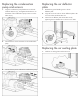
Replacement Instructions for the Water Temperature Sensor HP Modular Cooling System


b.
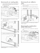
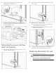
Connect the three large cables, starting from the right
and moving to the left, by pushing the cable into
the connector.
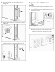
3. Using a T-25 Torx driver, secure the AC transfer switch
chassis to the water group controller chassis by inserting
four Torx screws.
CAUTION: To prevent damage to the cables and
ensure proper fit of the transfer switch chassis, be
sure to route all cables through the U-shaped
opening in the rear of the chassis.
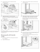
4. Slide the metal AC transfer switch box back into the
MCS unit on the sliding rails.
5. Complete the operation checklist.
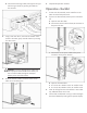
Operation checklist
1. If water was disconnected, restore water flow to the
MCS unit at the facility-side valve.
2. If power was disconnected, restore power to the MCS
unit.
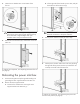
a. Open the rear MCS door.
b. Connect the network cable to the RJ-45 connector on
the power inlet box.
c. Connect the two AC power cables to the power
connectors on the power inlet box.
d. Open the front MCS door.
e. Turn on the AC1 breaker on the AC transfer switch.
f. Turn on the AC2 breaker on the AC transfer switch.
3. Clear all old logs from the web interface to ensure that
any additional alarms are current.
4. Confirm that no additional warning or alarm messages
have been detected by looking at the operator display.